Check patentability & draft patents in minutes with Patsnap Eureka AI!

Air pollutant detection device and detection method

A technology of air pollutants and detection devices, which is applied in the direction of measuring devices, color/spectral characteristic measurement, instruments, etc., can solve the problems of not using intelligent technology, detection devices that are difficult to apply for multiple gas detection, and gas adjustment with different concentrations.

Inactive Publication Date: 2018-10-09
王子剑
View PDF3 Cites 0 Cited by
  • Summary
  • Abstract
  • Description
  • Claims
  • Application Information

AI Technical Summary

Problems solved by technology

However, different gas chambers need to be replaced when detecting different gases, and it is difficult to detect multiple gases at the same time, and the gas absorption peak of a single component is generally affected by the actual gas, and there is an error in this calibration
[0008] The patent application with application number 2015106513566 designed an absorption cell with a long optical path. The absorption cell adopts a spiral structure, which reduces the volume of the absorption cell and improves the detection accuracy. However, the curved surface of the absorption cell is very difficult to process, and Its optical path is fixed, difficult to adjust, and cannot be adjusted for different concentrations of gases
[0009] In summary, the existing detection devices and detection methods are difficult to overcome the influence of temperature, humidity, and air pressure on the detection results, and a single detection device is difficult to apply to the detection of various gases. Single function, no intelligent technology, etc.

Method used


Image

  • Air pollutant detection device and detection method
  • Air pollutant detection device and detection method
  • Air pollutant detection device and detection method

Examples


Embodiment 1

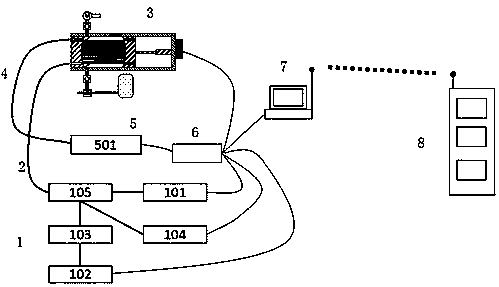
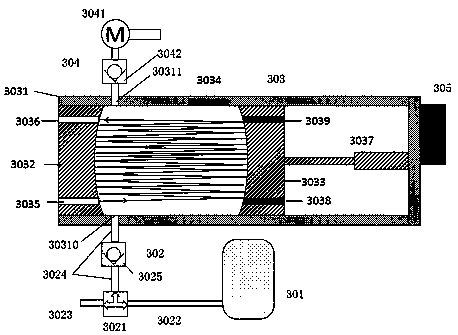
[0071] like figure 1 , figure 2 , an air pollutant detection device, comprising a laser emission module 1, an incident optical path 2, a detection module 3, an outgoing optical path 4, a laser receiving module 5, a control microcontroller 6, a computer 7, and a cloud server 8;

[0072] The laser emission module 1 includes: a modulation signal generator 101, a wavelength scanning signal generator 102, a current controller 103, a temperature controller 104, a laser 105, and a laser energy detector;

[0073] The incident optical path 2 and the outgoing optical path 4 are composed of optical fibers; one end of the incident optical path 2 is connected to the laser emitting module 1, and the other end is connected to the detection module 3; one end of the outgoing optical path 4 is connected to the laser receiving module 5, and the other end is connected to the detection module 3;

[0074] The laser receiving module 5 includes a spectrometer 501;

[0075] The laser emission modul...

Embodiment 2

[0087] This embodiment further describes the device of Embodiment 1.

[0088] A method for detecting atmospheric pollutants using the detection device of Embodiment 1, comprising the following steps:

[0089] 1) The computer 7 is connected to perform positioning through GPS, and obtains the temperature, humidity, air pressure, and pollutant concentration data of the current location through the cloud server 8;

[0090] 2) The computer 7 sends a start monitoring command to the control single-chip 6, the control single-chip 6 controls the laser emission module 1 to emit laser, the laser receiving module 5 receives the laser, the detection module 3 detects the pollutant concentration data, and controls the single-chip 6 to obtain the laser receiving module 5. The data is sent to the computer 7, and the computer 7 calculates according to the detection parameters and the data uploaded by the control single-chip 6 to obtain the detection results of air pollutants;

[0091] 3) The c...

Embodiment 3

[0123] Adopt the method of embodiment 2 to carry out the detection of various gases, specifically:

[0124] Set up SO via computer 2 The detection center wavelength of 2516nm, N 2 O: 2557nm, NO: 1800nm ​​or 2650nm, CO 2 : 2004nm or 2680nm, CO: 1563nm, NO 2 : 7.3 μm, O 3 : 9.6 μm.

[0125] For each of the above gases, one measurement was performed in the manner of Example 2, and the measurement results were compared with the results of the cloud server.


PUM


Abstract

The invention belongs to the field of gas detection, and particularly relates to a gas detection device, in particular to an air pollutant detection device and an air pollutant detection method. The air pollutant detection device comprises a laser transmitting module, an incident light path, a detection module, an emergent light path, a laser receiving module, a control single-chip computer, a computer and a cloud server. Atmosphere to be detected is converted into atmosphere with standard room temperature and is detected in a drying manner under standard atmospheric pressure, so that by suchthe detection method, an error caused by different temperatures, humidity and pressures during infrared absorption detection is avoided, and a result is more accurate without correction; the calculated pollutant concentration in the standard state is converted into the concentration of pollutants in the atmosphere in the current state, and the pollutant concentration can be compared with cloud data.

Description

technical field [0001] The invention belongs to the field of gas detection, in particular to a gas detection device, in particular to an atmospheric pollutant detection device and a detection method. technical background [0002] Air pollutants refer to those substances that are released into the atmosphere due to human activities or natural processes and have harmful effects on people and the environment. In a dry atmosphere, the composition of constant gases is negligible. However, in a certain range of atmosphere, trace substances that were not originally appeared, and their quantity and duration may have adverse effects and harm on people, animals, plants, objects, and materials. When the concentration of pollutants in the atmosphere reaches a harmful level, and even destroys the conditions for the normal survival and development of the ecosystem and human beings, the phenomenon that causes harm to people or things is called air pollution. [0003] Air pollutants can b...

Claims


Application Information

Patent Timeline
Patent Type & Authority Patents(China)
IPC IPC(8): G01N21/01G01N21/39
CPCG01N21/01G01N21/39
Inventor 王子剑荆慧孙海生董建芳
Owner 王子剑
Features
  • R&D
  • Intellectual Property
  • Life Sciences
  • Materials
  • Tech Scout
  • Unparalleled Data Quality
  • Higher Quality Content
  • 60% Fewer Hallucinations
Learn More