ESD protection circuit based on enhanced PHEMTs

An ESD protection and enhanced technology, applied in the direction of emergency protection circuit devices, emergency protection circuit devices, circuit devices for limiting overcurrent/overvoltage, etc. complex problems, to achieve the effect of low cost, reduced load capacitance, and increased on-voltage

Pending Publication Date: 2018-06-01
SUZHOU RONGXIN MICROELECTRONICS CO LTD
View PDF0 Cites 0 Cited by
  • Summary
  • Abstract
  • Description
  • Claims
  • Application Information

AI Technical Summary

Problems solved by technology

[0005] The disadvantage of using an external ESD protection circuit is that additional components and PCB wiring are required, the structure is complex, and the cost is high
[0006] The ESD protection circuit using internal depletion-type tubes cannot adapt to high-power circuits, and its large parasitic capacitance will affect high-frequency signals

Method used


Image

  • ESD protection circuit based on enhanced PHEMTs
  • ESD protection circuit based on enhanced PHEMTs

Examples


Embodiment Construction

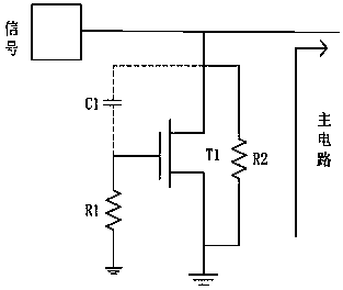
[0031] combine figure 2 , which describes the first specific embodiment of the present invention in detail, but does not limit the claims of the present invention in any way.

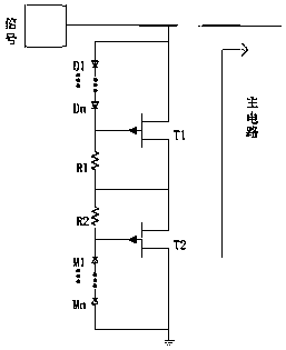
[0032] Such as figure 2 As shown, an enhanced PHEMT-based ESD protection circuit includes an ESD bias circuit and a resistor, and also includes two enhanced PHEMT tubes T1 and T2 connected in series, the source of T1 is connected to the source of T2, The drain of the T1 is connected to the chip pad that needs ESD circuit protection, and the drain of the T2 is grounded;

[0033] There are two ESD bias circuits, which are respectively connected between the drain and the gate of the T1 and between the gate and the drain of the T2;

[0034] There are two resistors, namely R1 and R2, the resistor R1 is connected between the gate and the source of the T1, and the resistor R2 is connected between the source and the gate of the T2.

[0035] More specifically, the ESD bias circuit includes several diodes co...


PUM


Abstract

The invention relates to an ESD (Electro-Static Discharge) protection circuit based on enhanced PHEMTs (Pseudomorphic High Electron Mobility Transistor), comprising ESD bias circuits and resistors. The ESD protection circuit further comprises two enhanced PHEMTs T1 and T2 connected in series. The source of T1 is connected with the source of T2. The drain of T1 is connected to a chip pad needing ESD circuit protection. The drain of T2 is grounded. The two ESD bias circuits are respectively connected between the drain and the gate of T1 and between the gate and the drain of T2. A resistor R1 isconnected between the gate and the source of T1. A resistor R2 is connected between the source and the gate of T2. The enhanced PHEMTs are connected in series in a back-to-back manner to form the ESDprotection circuit, which can reduce the load capacitance and make the ESD protection circuit applicable to high-frequency circuits. An ESD bias voltage is provided by connecting a plurality of diodesin series, which can improve the turn-on voltage of the ESD circuit and make the ESD protection circuit applicable to occasions with high input power. Moreover, the ESD protection circuit can be implemented inside a chip, and the implementation cost is low.

Description

technical field [0001] The invention relates to an ESD protection circuit, in particular to an enhanced PHEMT-based ESD protection circuit. Background technique [0002] When designing high-frequency, high-power microwave circuits, people often use gallium arsenide pHMET (Pseudomorphic High Electron Mobility Transistor in English, Chinese [0003] This article refers to quasi-high electron mobility transistor) devices, such as antenna switches, low-noise amplifiers, and power amplifiers, but the ESD performance of the pHMET device itself is very poor, and the ESD (Electro-Static discharge) voltage human body model is only 100-250V. Therefore, an ESD protection circuit needs to be added in the PHEMT chip. At present, the ESD protection circuit of pHMET is basically connected externally, and the implementation cost is high. Even if there is an ESD protection circuit implemented inside the chip, it is not suitable for high-power input occasions. The invention aims at the hig...

Claims


Application Information

Patent Timeline
IPC IPC(8): H02H9/04
CPCH02H9/045
Inventor 曹然
Owner SUZHOU RONGXIN MICROELECTRONICS CO LTD
Why Eureka
Try Eureka