
A three-stage generator/generator DC excitation control method with two-phase excitation structure

A DC excitation and generator technology, applied in the direction of controlling generators through magnetic field changes, can solve the problems of poor winding utilization, poor stator and rotor energy transmission, low excitation efficiency, etc., to ensure stable control, reduce volume and weight, Easy to program and operate

Active Publication Date: 2021-03-26
SHAANXI AVIATION ELECTRICAL
View PDF5 Cites 0 Cited by
  • Summary
  • Abstract
  • Description
  • Claims
  • Application Information

AI Technical Summary

Problems solved by technology

Among them, the single-phase AC excitation is limited by the capacity of the exciter body and the amplitude of the power supply voltage, the excitation efficiency is not high, and the energy transmission of the stator and rotor is poor.
For three-phase AC excitation, the structural design of the motor body needs to be greatly changed, the utilization rate of the winding is poor, and the switching method of AC and DC excitation is complicated
[0005] Regarding the state of power generation, the above-mentioned patent only describes the way of direct current excitation current, but does not propose a specific control method, nor does it explain the control law of excitation current, so that the three-stage generator / generator with two-phase excitation structure The specific implementation of DC excitation control becomes difficult

Method used


Image

  • A three-stage generator/generator DC excitation control method with two-phase excitation structure
  • A three-stage generator/generator DC excitation control method with two-phase excitation structure
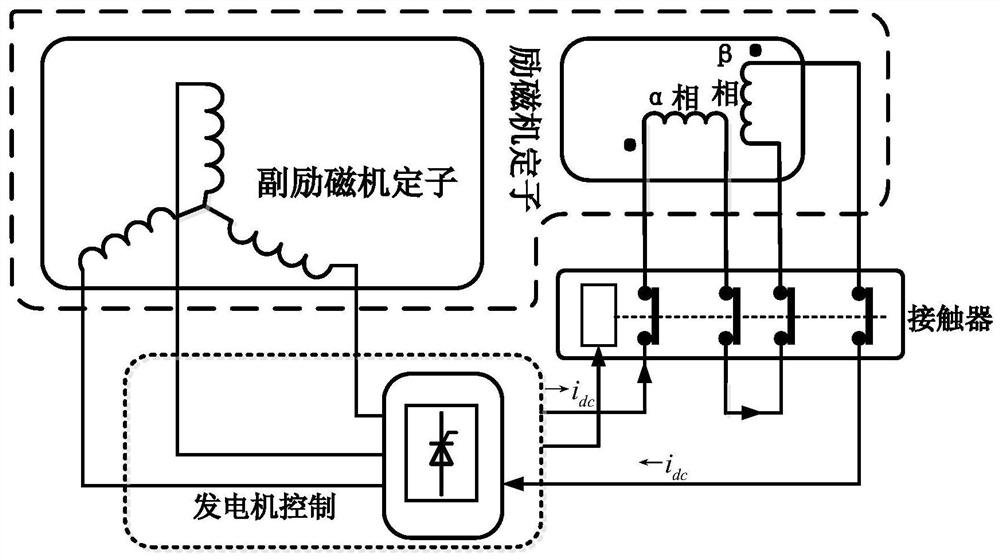
  • A three-stage generator/generator DC excitation control method with two-phase excitation structure

Examples


Embodiment Construction

[0023] The present invention will be described in further detail below in conjunction with the accompanying drawings.

[0024] The invention proposes a three-stage starter / generator constant speed voltage product DC excitation control method with a two-phase excitation structure. The control method can ensure that the main generator excitation current remains stable during the power generation process of the three-stage starter / generator.

[0025] A three-stage starter / generator constant speed voltage product DC excitation control method with a two-phase excitation structure, characterized in that the stator of the three-stage starter / generator main exciter adopts two-phase symmetrical excitation windings, and after the motor starts to reach a certain speed, it passes The corresponding contactor connects the two-phase excitation windings of the main exciter in reverse series to form a one-phase winding. By adjusting and controlling the product of the DC voltage amplitude genera...


PUM


Abstract

The invention belongs to the technical field of two-phase excitation structure three-level type electrizer / generator control, and relates to a direct current excitation control method based on constant speed and voltage product. The method comprises the following steps: setting the product of direct current excitation input voltage Udc and electrizer / generator speed n as a constant, calculating the direct current excitation input voltage Udc according to the collection value of the electrizer / generator speed n, and obtaining the direct current excitation input voltage Udc according to the calculation so as to obtain exciter rotor three-phase output target voltages Ua, Ub and Uc. According to the two-phase excitation structure three-level type electrizer / generator direct current excitationcontrol method based on constant speed and voltage product provided by the invention, the product of motor speed and main exciter stator additional direct current exciting voltage amplitude is adjusted to be unchanged, so that stable main exciter three-phase alternating current output amplitude can be guaranteed, then sufficient stable exciting current is provided for the power generation processof a main generator, and stable control for three-level type electrizer / generator power generation output voltage is guaranteed.

Description

technical field [0001] The invention belongs to the technical field of two-phase excitation structure three-stage generator / generator control, and relates to a DC excitation control method based on constant speed voltage product. Background technique [0002] At present, aviation AC power systems mostly use three-stage brushless motors as alternators, which are mainly composed of main generators, main exciters, auxiliary exciters (permanent magnet machines) and rotary rectifiers. Motors are also widely used in the fields of electric vehicles and wind power generation systems. In order to reduce the weight of the equipment and increase the power density, this type of motor is often designed to operate in both the power generation state and the electric state. The technical difficulty mainly lies in the excitation of the two states. With the improvement of airborne electrical equipment and power level, the capacity of the three-stage generator / generator is getting larger and ...

Claims


Application Information

Patent Timeline
Patent Type & Authority Patents(China)
IPC IPC(8): H02P9/14
CPCH02P9/14
Inventor 刘文昉周鑫姜宇段晓丽
Owner SHAANXI AVIATION ELECTRICAL
Learn More