
Cascade device and cascade system of laser wakefield accelerator

A technology of laser wake field and cascading device, applied in accelerators, electrical components, etc., to achieve the effects of stable quality, simple and compact device, and simple operation

Active Publication Date: 2019-09-24
SHANGHAI JIAOTONG UNIV
View PDF7 Cites 0 Cited by
  • Summary
  • Abstract
  • Description
  • Claims
  • Application Information

AI Technical Summary

Problems solved by technology

However, in this scheme, complex plasma mirrors and active plasma lenses need to be installed in the cascading area of ​​the device, and at the same time, it is necessary to achieve time and energy matching between the electron beam and the active plasma mirror. The cascade acceleration of the

Method used


Image

  • Cascade device and cascade system of laser wakefield accelerator
  • Cascade device and cascade system of laser wakefield accelerator
  • Cascade device and cascade system of laser wakefield accelerator

Examples


Embodiment 1

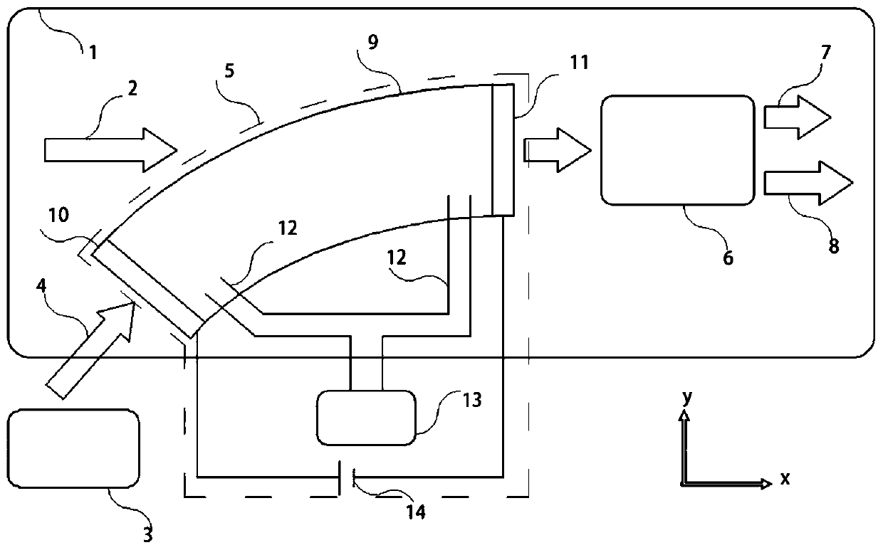
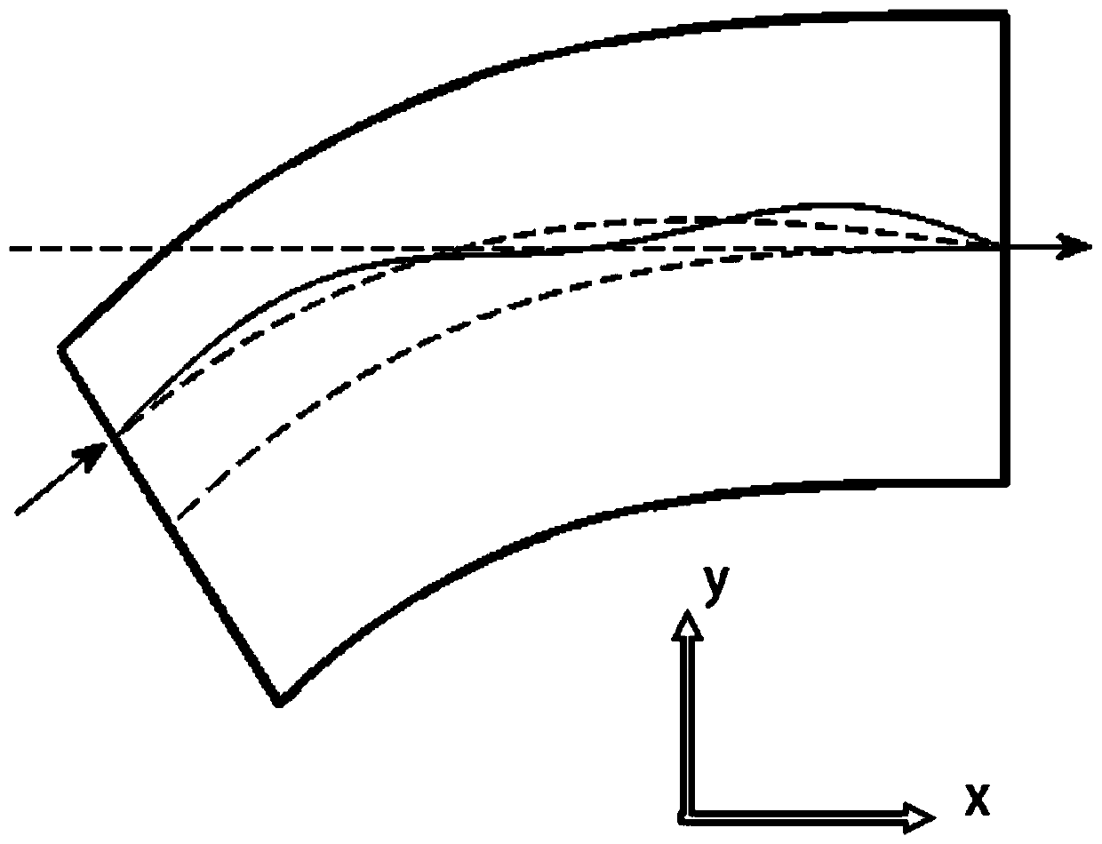
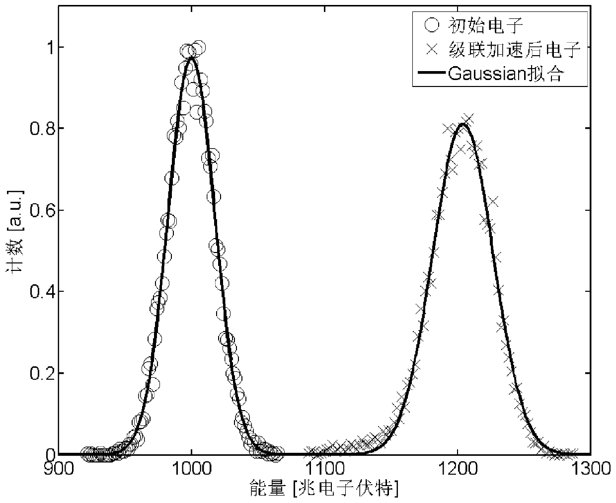
[0059] This embodiment adopts figure 1 The laser wakefield accelerator cascade device, wherein the length of the front-stage outgoing electron beam is 2 microns, the width is 1 micron, the energy is 1000 MeV, the full-width half-height energy dispersion is 5%, and the post-stage laser beam is based on Modular Gaussian beam, the pulse wavelength is 0.8 microns, the laser beam pulse width is 20 femtoseconds, the focal spot radius at the focal point is 8 microns, and the peak power density is 5.5×10 18 Watts per square centimeter. The length of the bent capillary is 2 mm, the initial bending radius is 10 mm, and the final bending radius tends to infinity. The laser is incident vertically from the outside of the front end of the curved capillary, 6.33 microns away from the center. The electron density in the center of the plasma channel formed after discharge is 1.5×10 18 per cubic centimeter.

[0060] The results obtained from the numerical simulation show that the laser wake...


PUM


Abstract

The invention discloses a laser wake-field accelerator cascade device and a cascade system. The cascade device comprises a vacuum chamber, a post-laser, the cascade system and a post laser wake-fieldaccelerator. The cascade system comprises a tortuous capillary, a front-end electrode plate, a rear-end electrode plate, an inflation pipeline and a gas generation device. The two ends of the tortuouscapillary are provided with the front-end electrode plate and the rear-end electrode plate. The internal part of the tortuous capillary is communicated with the gas generation device through fluid. The tortuous capillary and the post laser wake-field accelerator are arranged in the vacuum chamber. The front-end electrode plate and the rear-end electrode plate are used for being connected with a power supply and forming voltage difference so that the gas molecules in the tortuous capillary is enabled to be ionized. The ionized gas molecules repetitively discharge to generate plasma distribution which has uniform density distribution along the axial direction of the capillary and small radial center density and large external density. The laser wake-field accelerator cascade device has theadvantages that the device is simple, compact and practicable, high in cascade efficiency and stable in electron beam quality before and after cascading.

Description

technical field [0001] The invention relates to the field of laser acceleration, in particular to a laser wakefield accelerator cascade device and a cascade system. Background technique [0002] The concept of accelerating electrons by using the wake field generated by ultrashort and ultraintense lasers propagating in plasmas below the critical density was first proposed by Tajima and Dawson in 1979. As the laser propagates through the plasma, it excites a plasma wave of electrons behind the laser pulse, known as the laser wake. The longitudinal electric field in the laser wake traps and accelerates specific electrons, achieving high-energy electron acceleration. Since the intensity of the laser wake field is not limited by the usual material damage threshold, it can be three orders of magnitude higher than that of the usual radio frequency field accelerator. Therefore, the acceleration system based on it has the advantages of small scale, large acceleration gradient, and h...

Claims


Application Information

Patent Timeline
Patent Type & Authority Patents(China)
IPC IPC(8): H05H15/00
Inventor 罗辑陈民盛政明张杰迪诺雅罗辛斯基
Owner SHANGHAI JIAOTONG UNIV
Learn More