Polishing machine and polishing equipment

A polishing machine and equipment technology, applied in the direction of grinding/polishing equipment, surface polishing machine tools, metal processing equipment, etc., can solve the problems of low polishing rate between polishing abrasives and workpieces, slow drum speed, uneven polishing, etc. Achieve the effects of good fixing effect, reliable connection relationship and low cost

Pending Publication Date: 2018-06-05
河北金音乐器集团有限公司
View PDF16 Cites 6 Cited by
  • Summary
  • Abstract
  • Description
  • Claims
  • Application Information

AI Technical Summary

Problems solved by technology

[0005] The first object of the present invention is to provide a polishing machine, in order to solve the problem of low polishing rate and uneven polishing between the polishing abrasive in the drum and the workpiece due to the slow speed of the drum in the existing drum polishing machine

Method used


Image

  • Polishing machine and polishing equipment
  • Polishing machine and polishing equipment
  • Polishing machine and polishing equipment

Examples


Embodiment

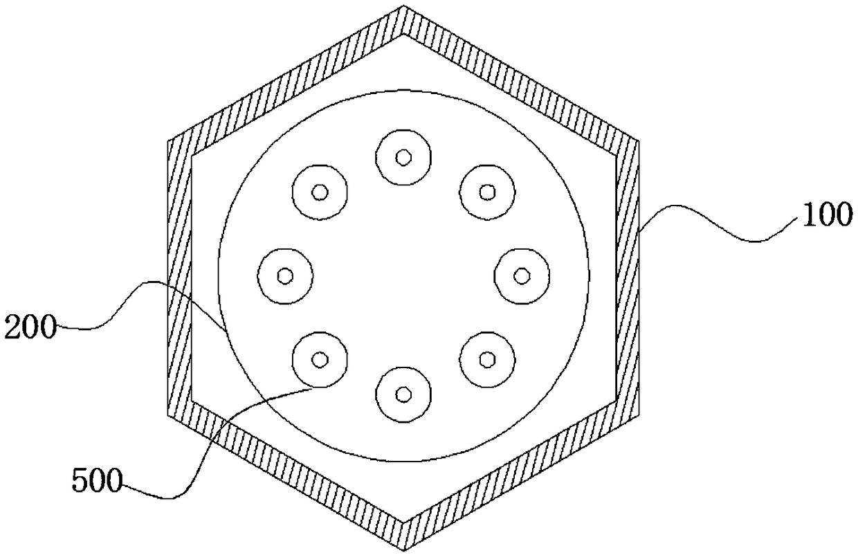
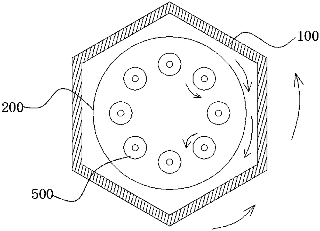
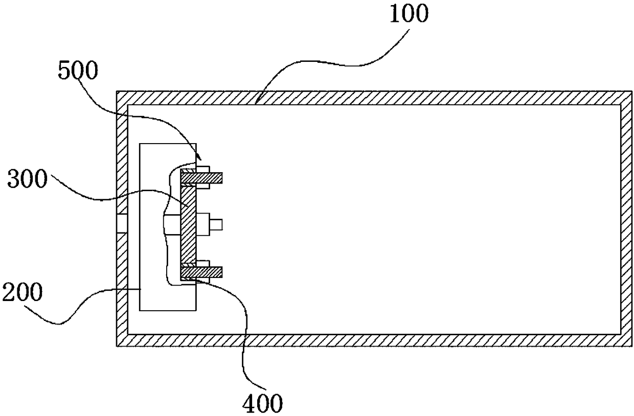
[0045] Such as Figure 1 to Figure 4 As shown, the present embodiment provides a polishing machine, including: a cylinder 100, an abrasive (not shown in the drawings) disposed in the cylinder 100, and a tray 200, the tray 200 is used to install a workpiece to be polished; the cylinder 100 and the tray 200 The rotation direction of the workpiece to be polished is opposite, and the workpiece to be polished is pivotally connected on the tray 200, and the rotation direction of the workpiece to be polished is the same as or opposite to that of the tray 200 (the rotation direction of the workpiece to be polished is opposite to that of the tray 200, see figure 2 shown); the cylinder 100 is connected with a first driving device for driving its rotation, and the workpiece to be polished and the pallet 200 are connected with a second driving device for driving both rotations; the cylinder 100, the workpiece to be polished and the pallet 200 are all around their own axis turn.

[0046]...


PUM


Abstract

The invention provides a polishing machine and polishing equipment, relates to the technical field of polishing equipment, and aims to the solve the technical problems that due to the fact that the rotation speed of the barrel of an existing barrel polishing machine is low, the polishing rate between an abrasive material in the barrel and a workpiece is low, and polishing is uneven. The polishingmachine comprises a barrel, an abrasive material and a support plate and is characterized in that the rotation direction of the barrel is opposite to the rotation direction of the support plate, and the rotation direction of a to-be-polished workpiece is identical with or opposite to the rotation direction of the support plate. The polishing equipment comprises a barrel, an abrasive material and two support plates and is characterized in that the two support plates are respectively arranged at the two opposite ends of the barrel; the rotation direction of the barrel is opposite to the rotationdirection of the support plates, and the rotation direction of a to-be-polished workpiece is identical with or opposite to the rotation direction of the support plates. The polishing machine and thepolishing equipment have the advantages that the workpiece can be polished by the polishing abrasive material in an omnibearing manner, the workpiece can be fast and evenly polished, machining time isreduced, and surface polishing degree is enhanced.

Description

technical field [0001] The invention relates to the technical field of polishing equipment, in particular to a polishing machine and polishing equipment. Background technique [0002] Polishing refers to the use of mechanical, chemical or electrochemical action to reduce the surface roughness of the workpiece to obtain a bright and smooth surface. Polishing is also the modification of the surface of the workpiece using polishing tools and abrasive particles or other polishing media. [0003] There are various polishing methods commonly used. Among them, barrel polishing is a method commonly used in various polishing methods. The commonly used equipment in the drum polishing method is a drum polishing machine. Before the drum polishing machine works, a large amount of steel balls, lime and abrasives are placed in the inclined tank-shaped drum in the rough throwing stage. When the drum polishing machine is working, the steel balls, lime or Abrasives, etc. roll and collide r...

Claims


Application Information

Patent Timeline
Patent Type & Authority Applications(China)
IPC IPC(8): B24B31/02B24B31/12
CPCB24B31/0224B24B31/12
Inventor 陈学孔周杰博
Owner 河北金音乐器集团有限公司
Why Eureka
Try Eureka