
Universal mechanism

A technology of universal mechanism and universal head, which is applied in the direction of measuring devices, instruments, surveying and navigation, etc., can solve the problems of low response characteristics, low reliability, and many intermediate transmission links, so as to reduce the size and weight and improve control The effect of precision and simplified structure

Active Publication Date: 2018-06-05
GUIZHOU AEROSPACE ELECTRONICS TECH
View PDF5 Cites 0 Cited by
  • Summary
  • Abstract
  • Description
  • Claims
  • Application Information

AI Technical Summary

Problems solved by technology

However, when these universal mechanisms are designed, they can usually only point to the front of the aircraft, and cannot detect flying objects in the rear or flying objects on the left and right sides, and cannot respond to other flying objects in the rear to the corresponding system. In addition, the traditional universal The mechanism uses a mechanical structure, which is designed to have a large volume, complex structure, heavy weight, and many intermediate transmission links. It requires high matching accuracy and low response characteristics.
[0003] 1) The traditional universal mechanism can only point to the front of the aircraft, and cannot detect the flying objects in the rear or the flying objects on the left and right sides, and cannot respond to the corresponding system. There are blind spots for the control and measurement of flying objects;
[0004] 2) In addition, the traditional universal mechanism uses a mechanical structure, which is designed to be large in size, complex in structure, heavy in weight, with many intermediate transmission links, high requirements for matching accuracy, and low response characteristics;
[0005] 3) The closed-loop control system is complex and has low reliability

Method used


Image

  • Universal mechanism

Examples


Embodiment Construction

[0019] The technical solution of the present invention is further described below, but the scope of protection is not limited to the description.

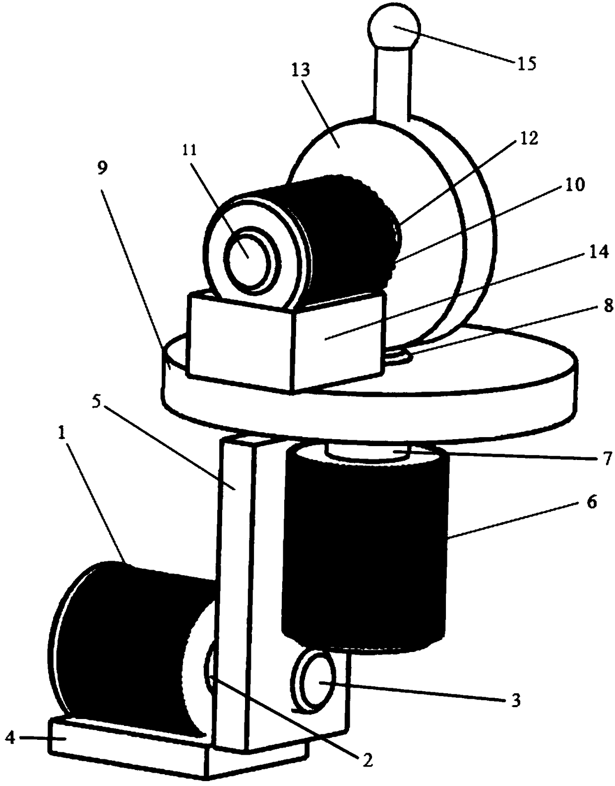
[0020] Such as figure 1 The shown universal mechanism is mainly composed of X-direction rotation mechanism, Y-direction rotation mechanism, Z-direction rotation mechanism, universal head and control system. Among them, the X-direction rotating mechanism is mainly composed of the first rotating motor 1, the first clutch 2, the electromagnetic clamp, the first shaft 3, the first mounting plate 4 and the rotating plate 5, and the Y-direction rotating mechanism is mainly composed of the second rotating motor 6 , a second clutch 7, an electromagnetic clamp, a second shaft 8 and a first circular rotating disk 9, and the Z-direction rotating mechanism is mainly composed of a third rotating motor 10, a third clutch 11, an electromagnetic clamp, and a third shaft 12. The second circular rotating disk 13 and the second mounting plate 14 are...


PUM


Abstract

The invention provides a universal mechanism which comprises a first rotating motor, a second rotating motor, a third rotating motor, a second circular rotating disc and a universal head, wherein thesecond rotating motor, the third rotating motor, the second circular rotating disc and the universal head are driven by the first rotating motor to rotate as a whole; the third rotating motor, the second circular rotating disc and the universal head are driven by the second rotating motor to rotate as a whole; the second circular rotating disc is driven by the third rotating motor to rotate; the universal head is fixed on a side surface of the second circular rotating disc; and rotating axes of the first rotating motor, the second rotating motor and the third rotating motor are perpendicular to one another. By adopting the universal mechanism, a flying article is detected without a dead angle by an aircraft, blind areas can be effectively avoided, a real universal function of the universalmechanism is achieved, application of mechanical structures is reduced, an automatic control system can be widely used, the structure is simplified, the size and the weight are reduced, the control precision is improved, and the rotation direction of the universal head can be conveniently adjusted.

Description

technical field [0001] The invention relates to a universal mechanism. Background technique [0002] During the launch flight of the aircraft, it is necessary to use the gimbal mechanism to measure the direction of the aircraft or targets in other directions. In order to achieve the mission of aircraft flight, the universal mechanism is widely used in certain disposable aircraft, such as the steering gear rotation mechanism inside the aircraft, the target tracking mechanism, etc. These universal mechanisms can correctly reflect the flight rotation of the aircraft , and adjust the direction in real time according to the received signal. However, when these universal mechanisms are designed, they can usually only point to the front of the aircraft, and cannot detect flying objects in the rear or flying objects on the left and right sides, and cannot respond to other flying objects in the rear to the corresponding system. In addition, the traditional universal The mechanism u...

Claims


Application Information

Patent Timeline
IPC IPC(8): G01C1/00B64F1/04
CPCB64F1/04G01C1/00
Inventor 石云陆
Owner GUIZHOU AEROSPACE ELECTRONICS TECH
Features
  • Generate Ideas
  • Intellectual Property
  • Life Sciences
  • Materials
  • Tech Scout
  • Unparalleled Data Quality
  • Higher Quality Content
  • 60% Fewer Hallucinations
Learn More