
Infrared image and low-light-level image fusion system and method

A low-light image and infrared image technology, which is applied in the field of images, can solve the problems such as the system and method that cannot provide infrared image and low-light image fusion.

Active Publication Date: 2018-06-05
SHENZHEN INST OF ADVANCED TECH
View PDF4 Cites 2 Cited by
  • Summary
  • Abstract
  • Description
  • Claims
  • Application Information

AI Technical Summary

Problems solved by technology

[0007] The purpose of the present invention is to provide a method and method for fusion of infrared images and low-light images, aiming to solve the problem that the existing technology cannot provide an infrared image and low-light images that conform to human vision, have clear targets, and have rich background details. System and method for image fusion

Method used


Image

  • Infrared image and low-light-level image fusion system and method
  • Infrared image and low-light-level image fusion system and method
  • Infrared image and low-light-level image fusion system and method

Examples


Embodiment 1

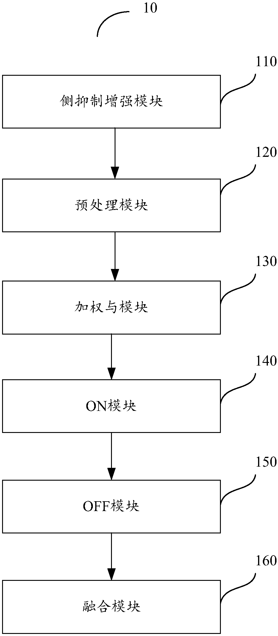
[0036] figure 1 The method 10 for fusing infrared images and low-light images provided by Embodiment 1 of the present invention is shown. For the convenience of illustration, only the parts related to the embodiment of the present invention are shown, including: side suppression enhancement module 110, preprocessing module 120 , weighted sum module 130 , central excitation-surround inhibition ON module 140 , central inhibition-surround excitation OFF module 150 and fusion module 160 .

[0037] The side suppression enhancement module 110 is configured to perform side suppression enhancement processing on infrared images (Infrared Radiation, IR) to obtain IR images, and perform side suppression enhancement processing on low light level images (Low light level, LLL) to obtain LLL images.

[0038] In the embodiment provided by the present invention, the side suppression enhancement module adopts a two-dimensional side suppression model, and its mathematical model is:

[0039] ...

Embodiment 2

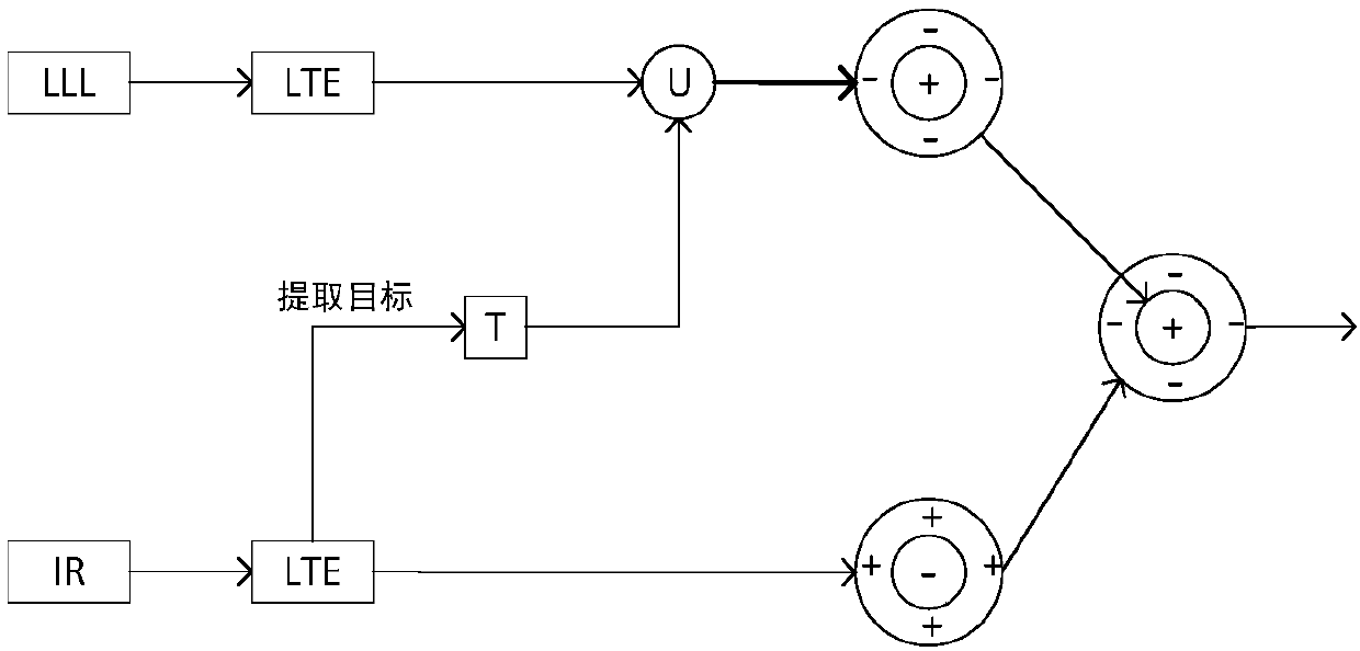
[0070] figure 2 It shows a schematic diagram of the realization of the method for fusing infrared images and low-light images provided by Embodiment 2 of the present invention. For convenience of description, only the parts related to the embodiment of the present invention are shown.

[0071] Among them: LLL (Low light level) is expressed as low-light image; IR (Infrared Radiation) is expressed as infrared image; LTE (Lateral inhibition Enhancement) is expressed as side suppression enhancement; T (target)

[0072] represented as the target image; Expressed as a weighted sum; Expressed as the central excitatory-surround inhibitory ON system; Expressed as a central inhibition-surround excitation OFF system.

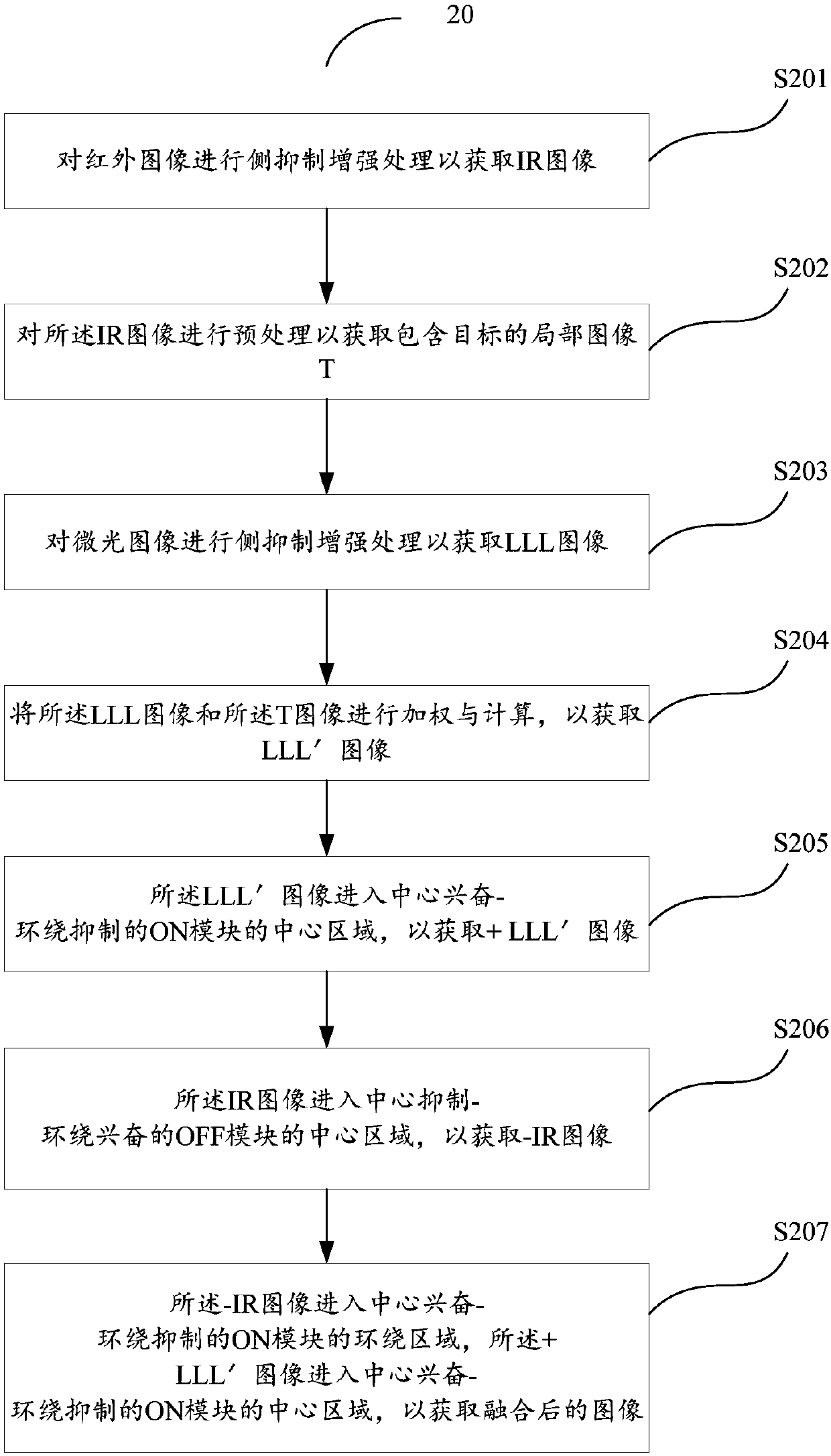
[0073] see image 3 , a flow chart 20 of the method steps for fusion of an infrared image and a low-light image provided by the present invention, detailed as follows:

[0074] In step S201, side suppression enhancement processing is performed on the infrared imag...


PUM


Abstract

The invention provides an infrared image and low-light-level image fusion system and method. According to the invention, lateral inhibition enhancement processing is performed on an infrared image anda low-light-level image to obtain an IR image and an LLL image, preprocessing is performed on the IR image to obtain a local image T, the LLL image and the T image are weighted and calculated to obtain an LLL' image, the LLL' image is processed to obtain a +LLL' image, the IR image is processed to obtain a -IR image, the -IR image enters a surrounding region of an ON module, the +LLL' enters a central region of the ON module, and a fused image is obtained. The infrared image and low-light-level image fusion system and method adopt a bionic biological vision ON-OFF model, and the infrared image passing through an OFF system and the low-light-level image passing through an ON system are respectively inputted into an inhibition region and an excitement region of the ON system, so that a fused image which conforms to the human eye vision and is clear in target and rich in background detail is obtained.

Description

technical field [0001] The invention belongs to the field of image technology, in particular to a system and method for fusing infrared images and low-light images. Background technique [0002] Because the infrared image is the image produced by the radiation of the object itself, it can "actively" obtain the target information in the scene, and can well display the hidden hot target, which is less affected by the lighting conditions and bad weather, but at the same time due to Due to the limitations of the imaging principle, the contrast of the infrared image is low, the spatial correlation is strong, the ability to reflect the target details is relatively poor, and the imaging effect does not conform to the visual habits of the human eye. [0003] Low-light images belong to the category of visible light, especially in low-light conditions. Compared with infrared images, the content information is richer, which can better describe the details of the environment. However, d...

Claims


Application Information

Patent Timeline
Patent Type & Authority Applications(China)
IPC IPC(8): G06T5/50G06T5/00
CPCG06T5/50G06T2207/10048G06T2207/20221G06T5/00
Inventor 李慧奇张阵赵国如宁运琨王磊
Owner SHENZHEN INST OF ADVANCED TECH
Learn More