Distortion tester

A technology of a tester and a length-measuring device, applied in the field of optical systems, can solve the problems of high working band requirements of the system under test, time-consuming and laborious test data recording, time-consuming and laborious installation and adjustment work, etc., so as to improve the measurement accuracy and measurement efficiency, The effect of repeated measurement accuracy improvement and structural stability

Active Publication Date: 2011-05-25
陕西光电子先导院科技有限公司
View PDF0 Cites 0 Cited by
  • Summary
  • Abstract
  • Description
  • Claims
  • Application Information

AI Technical Summary

Problems solved by technology

[0004] 1. Low measurement accuracy
In this method, the standard grid plate is used, and the adjustment error of the grid plate and the error of the engraving line greatly reduce the measurement accuracy; at the same time, due to direct observation by the human eye, the differences between individuals lead to aiming errors; coupled with the precision turntable The existence of factors such as angle error makes the measurement accuracy of distortion only reach ±3μm
[0005] 2. The installation and debugging work is complicated, the structure is unstable, and the test efficiency is low
Before the test, the center of the grid plate must first coincide with the optical axis of the objective lens under test. The installation and adjustment work is time-consuming and laborious. At least 3 to 5 testers are required to cooperate to complete the entire installation and adjustment work, and the stability after the adjustment is poor. , low repeatability
[0006] 3. High requirements on the operating band of the system under test
Since this method mainly relies on human eyes for aiming measurement, it is only suitable for testing optical systems in the visible light band
[0007] 4. Time-consuming and labor-intensive test data recording
In this method, all the data are manually recorded, and finally the data is input into the computer for processing. This method of recording and processing data will inevitably lead to some unnecessary gross errors.

Method used


Image

  • Distortion tester
  • Distortion tester
  • Distortion tester

Examples


Embodiment Construction

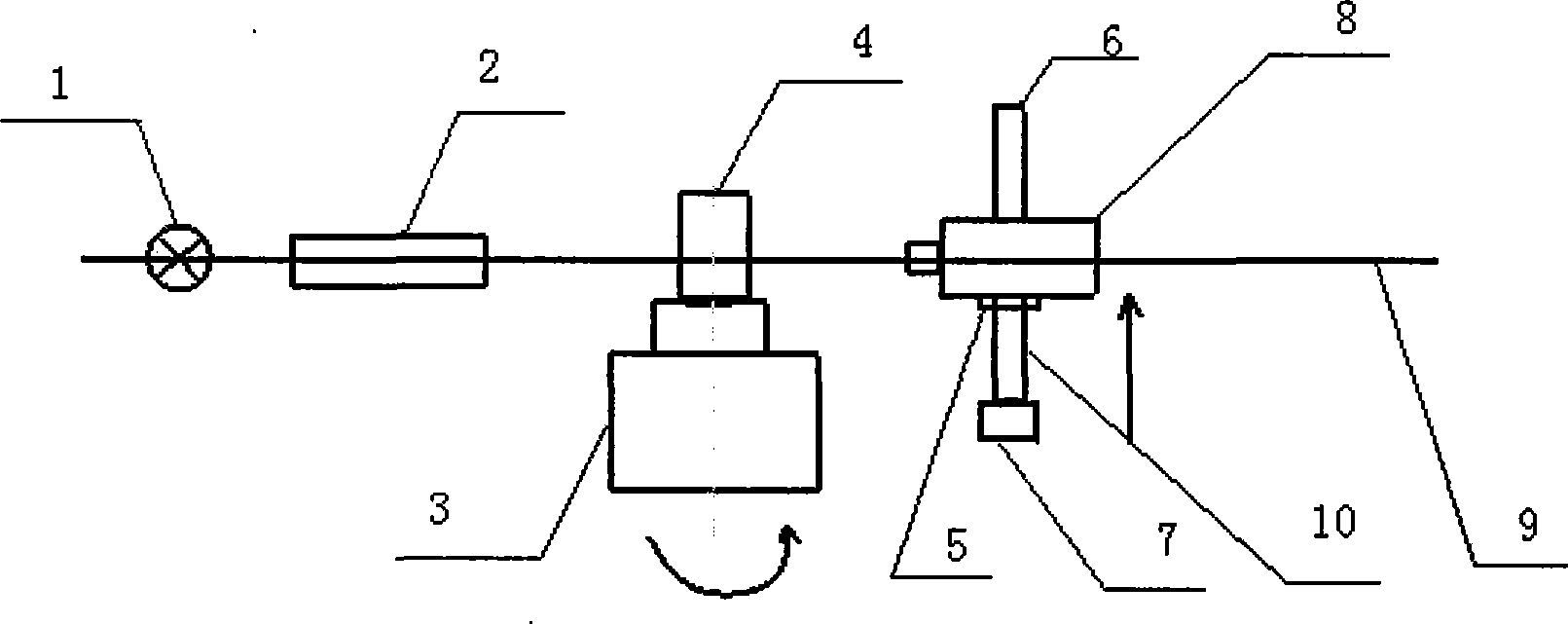
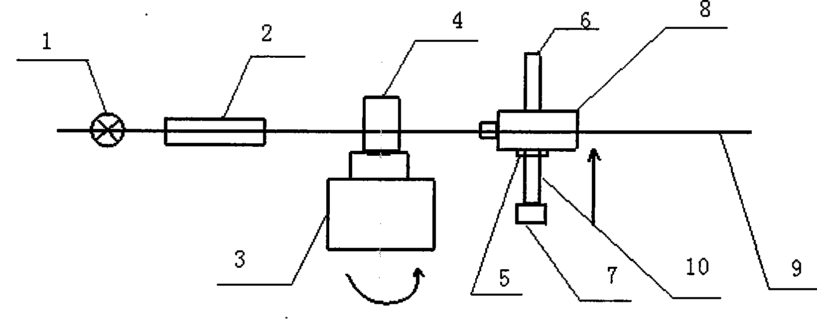
[0027] see figure 2 , the present invention provides a distortion tester, including a turntable 3, and the tester also includes a light source 1, a collimator 2, and a microscopic imaging system 8; the light source 1, the collimator 2, and the microscopic imaging system 8 are arranged on the same optical axis 9.

[0028] The high-precision distortion tester also includes a length measuring device 10 on which the microscopic imaging system 8 is fixed. The length measuring device 10 includes a laser interferometer 7, a reflector 5 and a two-dimensional precision guide rail 6; the reflector 5 is fixed on the lateral guide rail side of the two-dimensional guide rail 6; the normal line of the reflector 5 is perpendicular to the optical axis 9; The laser interferometer 7 emits beams perpendicular to the mirror 5 ; the laser interferometer 7 and the two-dimensional guide rail 6 are fixed on the length measuring device 10 . The two-dimensional precision guide rail 6 can also be an ...


PUM


Abstract

The invention relates to a distortion tester comprising a rotary table, a light source and a micro imaging system, wherein the light source and the micro imaging system are arranged on the same optical axis and are arranged on two sides of the rotary table. The invention provides a distortion tester which has high measurement precision, high efficiency, stable structure and expandable function.

Description

technical field [0001] The invention relates to the field of optical systems, in particular to a distortion tester. Background technique [0002] It is difficult for any optical system to meet the requirements of perfect imaging, but the magnitude of the aberration is different. The distortion of the optical system will directly affect the geometric position accuracy of the imaging target. Therefore, for precision measurement cameras, such as aerial measurement cameras, ballistic measurement cameras, CCD digital cameras, etc., the size of the distortion is a decisive factor for the measurement accuracy of the camera. In order to obtain accurate geometric position images, the optical design of the camera should not only correct the distortion as much as possible, but also need to carry out precise measurement of the distortion of the actual optical system, so as to provide the correction value in use. [0003] At present, the methods for detecting distortion in China adopt ...

Claims


Application Information

Patent Timeline
Patent Type & Authority Patents(China)
IPC IPC(8): G01M11/02G01B11/02
Inventor 赵建科张周锋周艳王锋王虎昌明
Owner 陕西光电子先导院科技有限公司
Why Eureka
Try Eureka