Outside-tower condensed heat-medium smoke plume elimination system for flue gas

A flue gas and whitening technology, applied in the field of flue gas whitening system, can solve the problems of wasting energy, large heat load of flue gas heating heat exchanger, limited space for use, etc. requirements, the effect of reducing dust and pollutants

Pending Publication Date: 2018-06-08
TIANJIN HUASAIER HEAT TRANSFER EQUIP
View PDF3 Cites 17 Cited by
  • Summary
  • Abstract
  • Description
  • Claims
  • Application Information

AI Technical Summary

Problems solved by technology

[0006] (1) In order to avoid condensation of water vapor in the flue gas, it is necessary to greatly increase the temperature of the flue gas, and the heat load of the flue gas heating heat exchanger is huge;
[0007] (2) Limited by the heat load, the flue gas heating heat exchanger is bulky, and most of the existing devices are renovation projects of the original devices, and the available space is limited, which cannot meet the actual needs
[0008] (3) Raising the temperature of the flue gas can only solve the appearance problem, that is, eliminate the "white fog" visible to the naked eye, and the water vapor entrained in the exhaust flue gas has not been reduced, so there is no substantial reduction in emission
[0009] In view of the above reasons, it is also necessary to reduce the amount of water vapor in the flue gas entering the chimney. One way is to continuously reduc

Method used


Image

  • Outside-tower condensed heat-medium smoke plume elimination system for flue gas
  • Outside-tower condensed heat-medium smoke plume elimination system for flue gas
  • Outside-tower condensed heat-medium smoke plume elimination system for flue gas

Examples


Embodiment Construction

[0041] In order to enable those skilled in the art to better understand the technical solutions of the present invention, the present invention will be further described in detail below in conjunction with the accompanying drawings and preferred embodiments.

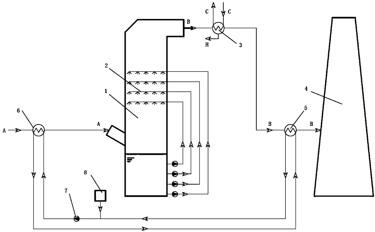
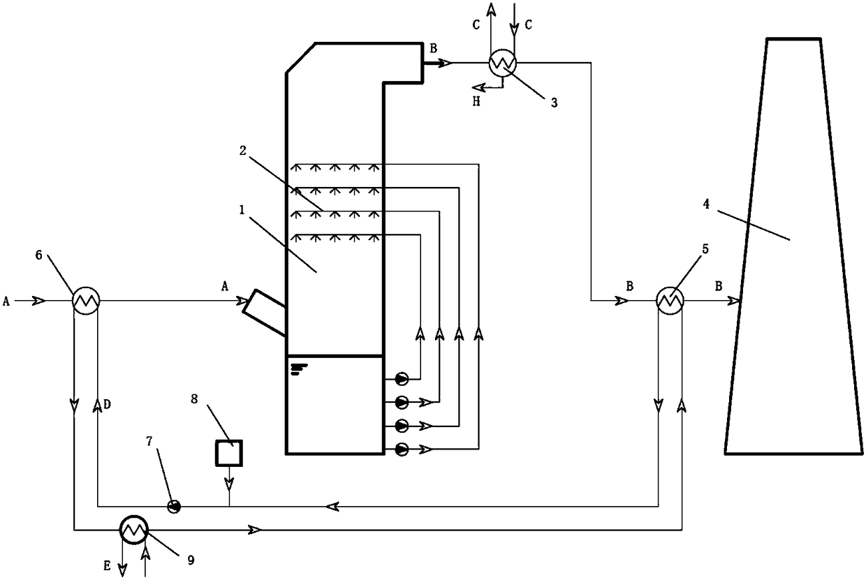
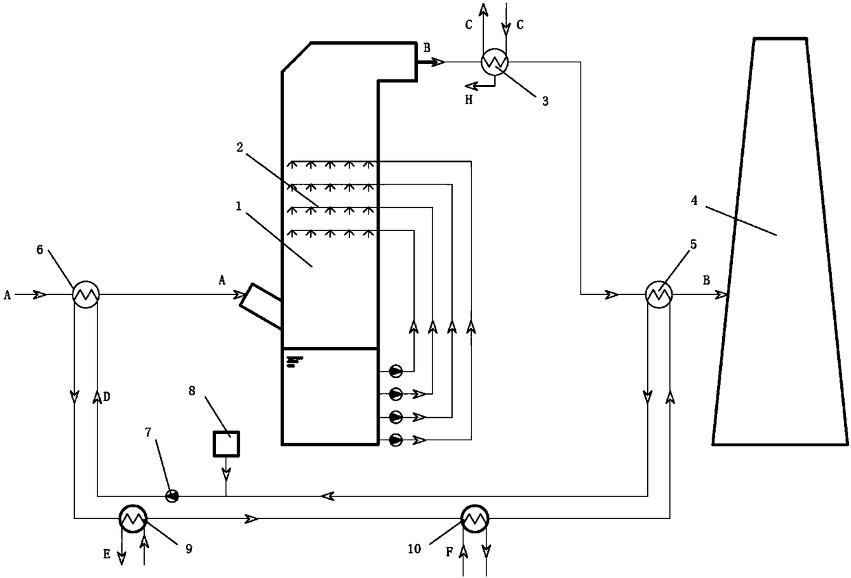
[0042] like figure 1 As shown, the present invention includes a cooling section heat exchanger 6, a desulfurization tower 1, a flue gas condenser 3, a heating section heat exchanger 5 and a chimney 4 through which the flue gas passes sequentially, wherein,

[0043] The heat exchanger in the cooling section is equipped with a flue gas flow channel for the heat exchanger in the cooling section and a heat medium flow channel for the heat exchanger in the cooling section. The flue gas outlet of the section heat exchanger;

[0044] The flue gas condenser is a plate heat exchanger, which is equipped with a flue gas condenser flue flow channel and a flue gas condenser cooling medium flow path, and the flue gas condenser flue g...


PUM


Abstract

The invention discloses an outside-tower condensed heat-medium smoke plume elimination system for flue gas, and relates to a smoke plume elimination system for desulfurized flue gas. The outside-towercondensed heat-medium smoke plume elimination system comprises a desulfurizing tower, a heat medium water closed cycle and a plate type flue gas condenser, wherein the heat medium water closed circleconsists of a temperature lowering section heat exchanger and a temperature raising section heat exchanger. Raw flue gas is cooled by heat medium water through the temperature lowering section heat exchanger and then enters the desulfurizing tower; desulfurized flue gas is cooled and dehumidified through the flue gas condenser, then enters the temperature raising section heat exchanger, and is discharged into the atmosphere through a chimney after being heated by the heat medium water; through the condensation, on purified flue gas, of the flue gas condenser, the reduction of the moisture content of the flue gas and the reduction of the smoke plume elimination heat load of the flue gas are realized; the purified flue gas is heated by utilizing the heat of the raw flue gas; the degree of superheat of the dehumidified flue gas is further improved; the elimination of a smoke plume and the abatement of the emissions of mill dust and water vapor are realized; as the flue gas condenser is arranged outside the system, condensed fluid separated out by the water vapor in the flue gas is discharged outside the system, and the influence cannot be generated to the water balance in the desulfurizing tower.

Description

technical field [0001] The invention relates to the application field of flue gas desulfurization, in particular to a flue gas whitening system condensed outside a tower. Background technique [0002] With the implementation of the "Emission Standard of Air Pollutants for Thermal Power Plants" (GB13226-2011) promulgated by the Ministry of Environmental Protection, it is required that the soot emission standard for coal-fired boilers should reach 30mg / Nm 3 , SO 2 The content is controlled at 100mg / m according to the difference between new and existing power plants 3 , 200mg / m 3 , soot and SO in key areas in the future 2 The emission is controlled at 20mg / m 3 , 50mg / m 3 . The increasingly stringent emission standards of air pollutants force coal-fired power plants and other coal-fired boiler enterprises to modify the flue gas emission system to meet the ultra-clean emission requirements. [0003] Coal-fired boilers use coal as energy, and produce a large amount of dust,...

Claims


Application Information

Patent Timeline
IPC IPC(8): B01D53/26B01D5/00
CPCB01D53/002B01D53/005B01D53/265B01D2259/652B01D2258/0283B01D2257/80
Inventor 宋秉棠王超
Owner TIANJIN HUASAIER HEAT TRANSFER EQUIP
Why Eureka
Try Eureka