Curve fitting method for ensuring global G2 continuity of tool path

A curve fitting and tool path technology, applied in the direction of digital control, electrical program control, etc., can solve problems such as application limitations, accelerated tool wear, part contour machining accuracy and poor surface quality.

Active Publication Date: 2018-06-08
HUAZHONG UNIV OF SCI & TECH
View PDF12 Cites 17 Cited by
  • Summary
  • Abstract
  • Description
  • Claims
  • Application Information

AI Technical Summary

Problems solved by technology

The existing tool path is usually expressed by small line segments. This processing mode has the following disadvantages: (1) The tool path is composed of a large number of data points, and the storage capacity is large; (2) The tool path only has G0 continuity, and the system frequently adds Slow down, it is easy to cause vibration of the machine tool, reduce processing efficiency, and accelerate tool wear; (3) The smoothness of the tool track is poor, and the machining accuracy and surface quality of the part contour are poor
Another method is to first ignore the continuity at the end points, fit the discrete data points into Bezier curves that meet the error requirements, and then use another Bezier curve for bridging processing to ensure the continuity of the local G2, so as to realize the spline as a whole. G2 continuous (Zhao Sheng, Bi Qingzhen, Wang Yuhan, etc. Tool path compression algorithm based on G2 continuous Bezier curve [J]. Journal of Shanghai Jiao Tong University, 2014, 48 (5)), the bridge curve of this method uses the middle two control points The overlapping cubic Bezier curve is only suitable for the case where the curvature of the spline splicing is 0, and the application is relatively limited

Method used


Image

  • Curve fitting method for ensuring global G2 continuity of tool path
  • Curve fitting method for ensuring global G2 continuity of tool path
  • Curve fitting method for ensuring global G2 continuity of tool path

Examples


specific Embodiment

[0079] The present invention provides a curve fitting method that ensures the overall G2 continuity of the tool track, comprising the following steps:

[0080] (1) Establish a B-spline curve;

[0081] According to the discrete tool trajectory, first identify the feature points, then divide the discrete data points between every two adjacent feature points into several small intervals, and finally establish the B-spline curve in sections. The present invention does not make too many descriptions on the B-spline segment fitting. For details, please refer to He S, et al. A chord error conforming tool path B-spline fitting method for NC machining based on energy minimization and LSPIA. Journal of Computational Design and Engineering (2015).

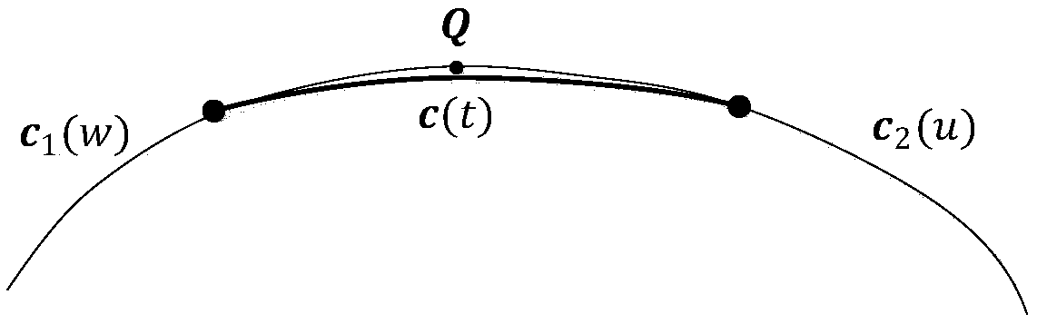
[0082] (2) Screen splines to determine the splines that need to be bridged

[0083] Not all splines are suitable for G2 bridging. Because the feature point is a point that cannot be changed, the spline curve segmented by the feature point ...


PUM


Abstract

The invention belongs to the field of computer aided manufacturing and numerical control machining and specifically relates to a curve fitting method for ensuring global G2 continuity of a tool path.The method comprises the following steps: to begin with, establishing a fitting curve in a piecewise manner according to the discrete tool path; then, carrying out spline screening to determine splines needing bridging processing; cutting off the splines participating in bridging processing; and finally, establishing a B spline having five control points as a bridging curve c(t) between the two cut-off points. By controlling data point error between the bridging curve c (t) and a given data point Q, it is ensured that the bridging curve meets machining error; by controlling shape maintenance constraint conditions of the bridging curve, the bridging curve meeting fairness requirements is obtained; and finally, a curve having global G2 continuity and meeting machining error requirements andfairness requirements is established. The method can ensure G2 continuity of joints of the splines, constructs the spline curve having global G2 continuity and enables a numerical control processing product to have higher precision and better machining quality.

Description

technical field [0001] The invention belongs to the field of computer-aided manufacturing and numerical control machining, and more specifically relates to a curve fitting method for ensuring the overall G2 continuity of tool tracks. Background technique [0002] In the field of computer-aided manufacturing and CNC machining, firstly, the tool path is calculated according to the surface to be processed through the CAD / CAM system, and then the tool path is converted into program code through post-processing, and finally the corresponding G code is transmitted to the CNC system. The existing tool path is usually expressed by small line segments. This processing mode has the following disadvantages: (1) The tool path is composed of a large number of data points, and the storage capacity is large; (2) The tool path only has G0 continuity, and the system frequently adds Slow down, it is easy to cause vibration of the machine tool, reduce processing efficiency, and accelerate tool...

Claims


Application Information

Patent Timeline
Patent Type & Authority Applications(China)
IPC IPC(8): G05B19/19
CPCG05B19/19
Inventor 李振瀚孙艳艳何姗姗江海清陈吉红
Owner HUAZHONG UNIV OF SCI & TECH
Why Eureka
Try Eureka