Interlocking vacuum switch and series compensation type current limiting device and method based on same

A vacuum switch and series compensation technology, applied in electrical switches, high-voltage/high-current switches, high-voltage air circuit breakers, etc., can solve problems such as increasing the complexity of the switch control system, increasing the cost and volume of materials, and reducing the reliability of line protection. , to achieve the effect of improving the actual breaking capacity and electrical life, improving system reliability and power quality, and reducing thermal shock

Pending Publication Date: 2018-06-08
XI AN JIAOTONG UNIV +1
View PDF0 Cites 13 Cited by
  • Summary
  • Abstract
  • Description
  • Claims
  • Application Information

AI Technical Summary

Problems solved by technology

If the switching of the above-mentioned series compensation and short-circuit fault current limiting functions is to be realized at the same time, two vacuum switches and two sets of independent operating mechanisms are required. In this case, the material, cost and volume are greatly increased, and the switch control system complexity, reducing the reliability of line protection

Method used


Image

  • Interlocking vacuum switch and series compensation type current limiting device and method based on same
  • Interlocking vacuum switch and series compensation type current limiting device and method based on same
  • Interlocking vacuum switch and series compensation type current limiting device and method based on same

Examples


Embodiment Construction

[0032] The interlock vacuum switch of the present invention and the series compensation type current limiting device applied thereto will be further described in detail below with reference to the accompanying drawings and specific embodiments.

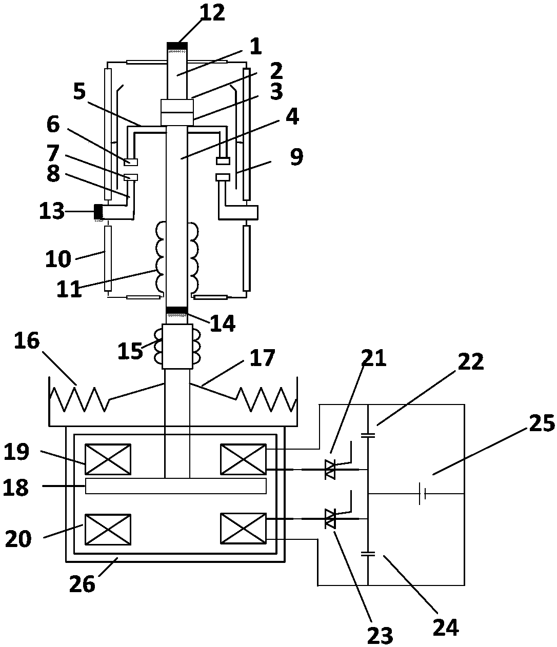
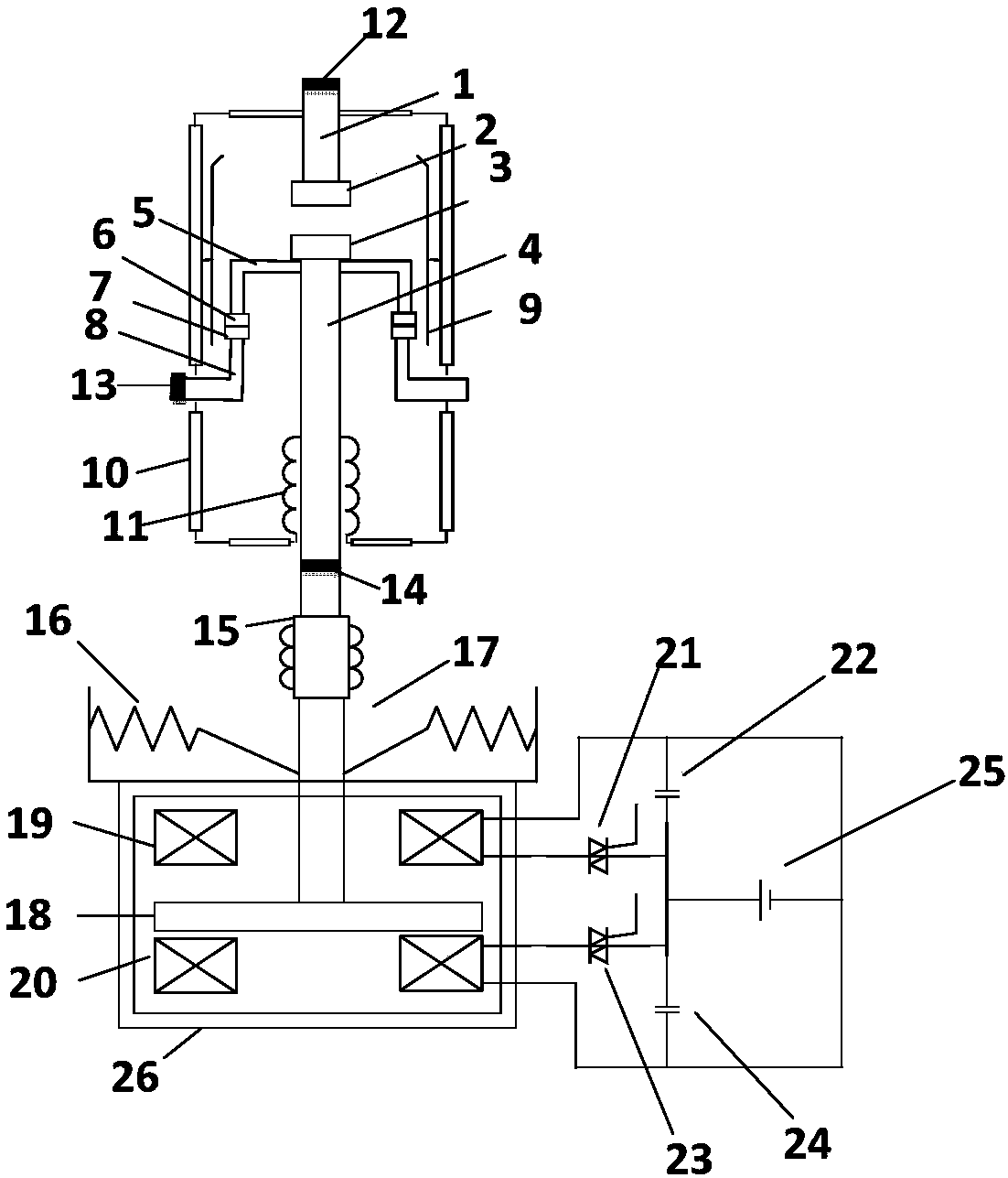
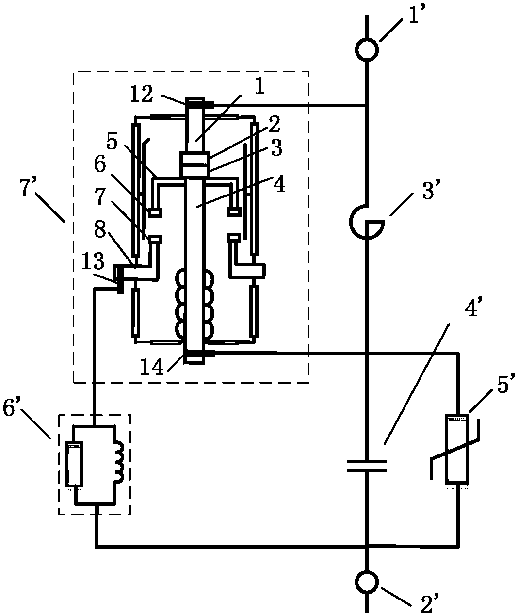
[0033] Such as figure 1 As shown, the interlock vacuum switch of the present invention is mainly composed of an interlock vacuum interrupter and a fast repulsion mechanism. The interlocking vacuum interrupter includes a static end side part, a moving end side part and a shell structure. The static end side part includes a static conductive rod 1 , a static main contact 2 , a metal flange 8 and a static auxiliary contact 7 . The upper end of the static conductive rod 1 is welded to the upper side of the insulating shell 10 and passes through, the lower end of the static conductive rod 1 is welded with the static main contact 2, the metal flange 8 is fixed in the middle of the insulating shell 10, and the upper end of the metal flange ...


PUM


Abstract

An interlocking vacuum switch and a series compensation type current limiting device and method based on the same are provided. The switch uses an interlocking vacuum interrupter. A fast repulsion mechanism is selected to cooperate with the interlocking vacuum interrupter to realize fast switching of the series compensation type current limiting device between the two functions of series compensation and current limiting. When the line of a traction network runs normally, a series compensation capacitor is accessed, and the device works in a series compensation state. When the line is short-circuited, an interlocking vacuum switch acts to short-circuit the capacitor, and a current limiting reactor is put into use in the system to limit the short circuit current of the line. Inside the sameinterrupter, a main static contact and a main moving contact constitute a first contact group to switch on/off the current limiting reactor, and an auxiliary static contact and an auxiliary moving contact constitute a second contact group to switch on/off the compensation capacitor. A single vacuum interrupter and a set of operating mechanism are adopted to realize the switching of a traction system between the functions of series compensation and current limiting. The volume cost and economic cost of the device can be reduced, and the reliability of the system can be improved.

Description

technical field [0001] The interlocking vacuum switch in the present invention belongs to the field of high-voltage vacuum switches, and specifically relates to an interlocking vacuum switch that uses a single vacuum switch to realize two different functions at the same time; System) comprehensive field of series compensation and current limiting technology, in particular to a series compensation type current limiting device and method based on an interlocked vacuum switch. Background technique [0002] The power supply of the electrified railway is to build several traction substations along the railway. The main task of the traction substation is to reduce the 110kV (or 220kV) three-phase alternating current from the power system to 27.5kV (or 2× 27.5kV) single-phase power, and then the single-phase power supply is sent to the catenary through the feeder line, and the catenary supplies power to the electric locomotive. However, on long slopes, heavy-duty lines and the end...

Claims


Application Information

Patent Timeline
Patent Type & Authority Applications(China)
IPC IPC(8): H01H33/662H01H33/664H01H33/666
CPCH01H33/662H01H33/664H01H33/666
Inventor 艾绍贵王启梅张哲刘志远姚晓飞史跃
Owner XI AN JIAOTONG UNIV
Why Eureka
Try Eureka