Check patentability & draft patents in minutes with Patsnap Eureka AI!

Electromagnetic injection valve and method for assembling electromagnetic injection valve

An injection valve and electromagnetic technology, which is applied in the field of solenoid fluid injection valves and assembled electromagnetic injection valves, can solve problems such as the cost impact of injection valves, and achieve the effects of improving magnetic properties, reducing total costs, and cost-effective

Active Publication Date: 2020-05-19
CONTINENTAL AUTOMOTIVE GMBH
View PDF6 Cites 0 Cited by
  • Summary
  • Abstract
  • Description
  • Claims
  • Application Information

AI Technical Summary

Problems solved by technology

However, the choice of material used for the housing can also have an important impact on the cost of the injection valve

Method used


Image

  • Electromagnetic injection valve and method for assembling electromagnetic injection valve
  • Electromagnetic injection valve and method for assembling electromagnetic injection valve
  • Electromagnetic injection valve and method for assembling electromagnetic injection valve

Examples


Embodiment Construction

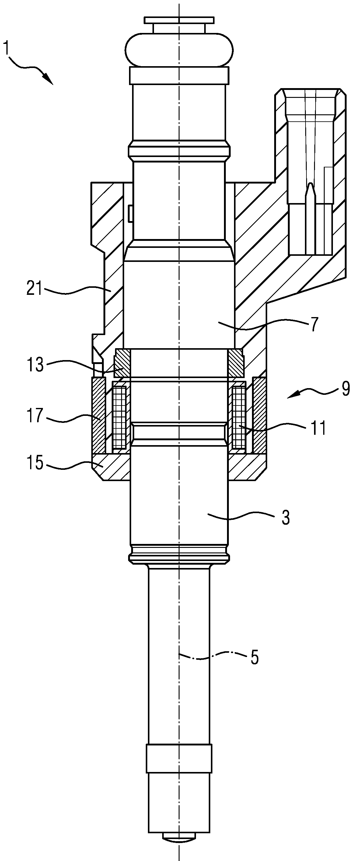
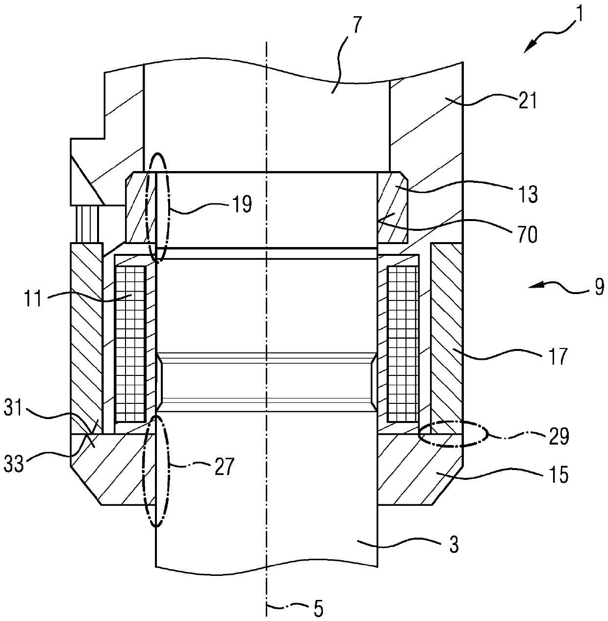
[0038] Figure 1 to Figure 3 The solenoid injector 1 shown is particularly suitable for dosing fuel to an internal combustion engine. However, the invention can also be used with other types of electromagnetic injection valves.

[0039] The injection valve 1 comprises a valve body 3 with a central longitudinal axis 5 and an inlet pipe 7 . The valve body 3 and the inlet pipe 7 form a cavity. The cavity is in figure 1 is not visible in figure 1 The valve body 3 and the inlet pipe 7 are shown only in side view, without sectioning. The cavity has a fluid outlet portion in communication with the fluid inlet portion. A fluid inlet part constituted by the inlet pipe 7 and a fluid outlet part constituted by the valve body 3 are located in particular at opposite axial ends of the injection valve 1 . In the cavity, the valve needle can move axially in order to seal and unseal the fluid outlet portion for controlling the flow of fluid out of the injection valve 1 .

[0040] The in...


PUM


Abstract

The present disclosure relates to internal combustion engines. Various embodiments may include an electromagnetic injection valve, particularly a solenoid type fluid injection valve for automotive applications. For example, an electromagnetic injection valve may include: an inlet tube; a valve body having a longitudinal axis and a cavity in which a valve needle moves; an upper magnetic ring press-fitted with the inlet tube or the valve body; a lower magnetic ring press-fitted with the valve body; and a housing part surrounding an electromagnetic actuator unit for moving the valve needle. The lower magnetic ring is positioned on the valve body in such a way that an upper side of the lower magnetic ring is in close contact with an underside of the housing part. The electromagnetic actuator unit abuts the upper magnetic ring and the lower magnetic ring on opposite axial sides. The housing part and / or the lower magnetic ring comprises a cut extending along the axis.

Description

technical field [0001] The invention relates to an electromagnetic injection valve, in particular to a solenoid type fluid injection valve applied to automobiles. Furthermore, the invention relates to a method of assembling an electromagnetic injection valve. Background technique [0002] A valve assembly for a fluid injection valve includes: a valve body including a cavity having a fluid inlet portion and a fluid outlet portion; and a valve needle axially movable within the cavity. The valve needle prevents fluid flow through the fluid outlet portion in a closed position and releases fluid flow through the fluid outlet portion in other positions. The valve needle is actuatable by an electromagnetic actuation unit. [0003] DE 103 12 319 A1 discloses an injection valve with a lower magnetic ring in order to improve the performance of the solenoid valve. [0004] In this type of injection valve, the housing is usually machined to create a recess for the coil and to fit the...

Claims


Application Information

Patent Timeline
IPC IPC(8): F02M51/06H01F7/16
CPCF02M51/0614F02M61/168F02M2200/08F02M2200/8061H01F2007/1676F02M51/0653F02M61/166F02M63/0019F02M2200/9061
Inventor S.菲利皮M.格兰迪F.伦齐V.波利多里
Owner CONTINENTAL AUTOMOTIVE GMBH
Features
  • R&D
  • Intellectual Property
  • Life Sciences
  • Materials
  • Tech Scout
  • Unparalleled Data Quality
  • Higher Quality Content
  • 60% Fewer Hallucinations
Learn More