A kind of lithography equipment and lithography system

A technology of lithography equipment and light beams, which is applied in the direction of optomechanical equipment, optics, instruments, etc., can solve the problems of low pattern accuracy, complex alignment steps, and low accuracy, so as to avoid translation steps and alignment steps, The effect of improving accuracy and improving alignment tolerance

Active Publication Date: 2020-01-10
HUAWEI TECH CO LTD
View PDF6 Cites 0 Cited by
  • Summary
  • Abstract
  • Description
  • Claims
  • Application Information

AI Technical Summary

Problems solved by technology

Currently, lithography equipment forms interference patterns through a single focusing lens. When periodic patterns need to be prepared on a larger substrate surface, the support carrying the substrate needs to be translated by a translation stepping device and requires complicated alignment steps. Due to The translational stepping device is expensive and the accuracy is not high, and the existing lithography equipment has the problems of low processing efficiency and low precision of the formed pattern

Method used


Image

  • A kind of lithography equipment and lithography system
  • A kind of lithography equipment and lithography system
  • A kind of lithography equipment and lithography system

Examples


Embodiment Construction

[0035] The following will clearly and completely describe the technical solutions in the embodiments of the present invention with reference to the drawings in the embodiments of the present invention. Obviously, the described embodiments are part of the embodiments of the present invention, not all of them.

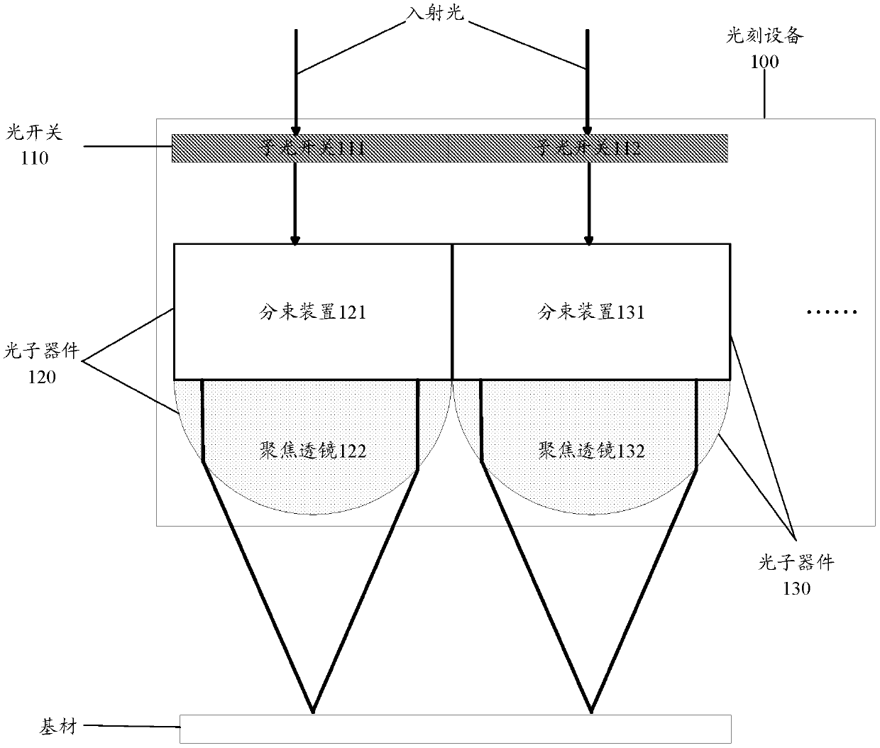
[0036] figure 1 A schematic plan view of a lithographic apparatus 100 according to an embodiment of the present invention is shown. Such as figure 1 As shown, the lithographic apparatus 100 of the embodiment of the present invention includes: an optical switch 110 , a photonic device 120 and a photonic device 130 .

[0037] The optical switch 110 includes a sub-optical switch 111 and a sub-optical switch 112 , the sub-optical switch 111 corresponds to the photonic device 120 , and the sub-optical switch 112 corresponds to the photonic device 130 . Taking the sub-optical switch 111 as an example, the state of the sub-optical switch 111 includes an on state and an off st...


PUM


Abstract

A lithographic apparatus (100) and a lithographic system, the lithographic apparatus (100) comprising: an optical switch (110) and N photonic devices (120). The optical switch (110) comprises N sub-optical switches (111, 112), and the N sub-optical switches (111, 112) correspond one by one to N photonic devices (120, 130), N being a positive integer greater than or equal to 2; states of each of the sub-optical switches (111, 112) comprise an on state and an off state, sub-optical switches (111, 112) in the on state are used for transmitting a light beam to a corresponding photonic device (120, 130), and sub-optical switches (111, 112) in the off state cannot transmit a light beam to a corresponding photonic device (120, 30); and each photonic device (120, 130) comprises beam splitting devices (121, 131) and focusing lenses (122, 132). The lithographic apparatus (100) may prepare a required pattern without changing a relative position of the lithographic apparatus (100) to a substrate, thus avoiding steps of translation and alignment, and thereby improving processing efficiency and accuracy of an interference pattern formed on the substrate.

Description

technical field [0001] The invention relates to the field of semiconductor preparation, in particular to a photolithography equipment and a photolithography system. Background technique [0002] Lithography refers to the method of forming a circuit pattern on a substrate by photocopying a mask or using interference light during the manufacturing process of a wafer. Currently, lithography equipment forms interference patterns through a single focusing lens. When periodic patterns need to be prepared on a larger substrate surface, the support carrying the substrate needs to be translated by a translation stepping device and requires complicated alignment steps. Due to The translational stepping device is expensive and has low precision, and the existing photolithography equipment has the problems of low processing efficiency and low precision of formed patterns. Contents of the invention [0003] In view of this, the implementation of the present invention provides a lithog...

Claims


Application Information

Patent Timeline
Patent Type & Authority Patents(China)
IPC IPC(8): G03F7/213
CPCG03F7/213
Inventor 弗洛里安·朗诺斯
Owner HUAWEI TECH CO LTD
Why Eureka
Try Eureka