
Material transferring device for automatic vision detection system of motor commutators

A motor commutator, visual inspection technology, applied in conveyor objects, transportation and packaging, object stacking and other directions, can solve the problems of random defect parts, high labor cost, easy to appear visual fatigue, etc., to improve intelligence , the effect of easy to grasp

Active Publication Date: 2018-06-12
重庆晓渝机器人有限公司
View PDF12 Cites 0 Cited by
  • Summary
  • Abstract
  • Description
  • Claims
  • Application Information

AI Technical Summary

Problems solved by technology

However, due to the many defect modes of the product, random defect locations, and inconspicuous defect characteristics, etc., there are high requirements for the judgment ability of the inspectors; in addition, if the number of products is large, manual inspection is prone to visual fatigue, and missed inspections occur from time to time. , and high labor costs
[0003] In view of the limitations of the existing commutator quality control mode, the automatic inspection system developed by our company adopts machine vision technology to solve the problems of poor reliability and high labor cost of existing manual inspection

Method used


Image

  • Material transferring device for automatic vision detection system of motor commutators
  • Material transferring device for automatic vision detection system of motor commutators
  • Material transferring device for automatic vision detection system of motor commutators

Examples


Embodiment Construction

[0026] The present invention will be described in further detail below by means of specific embodiments:

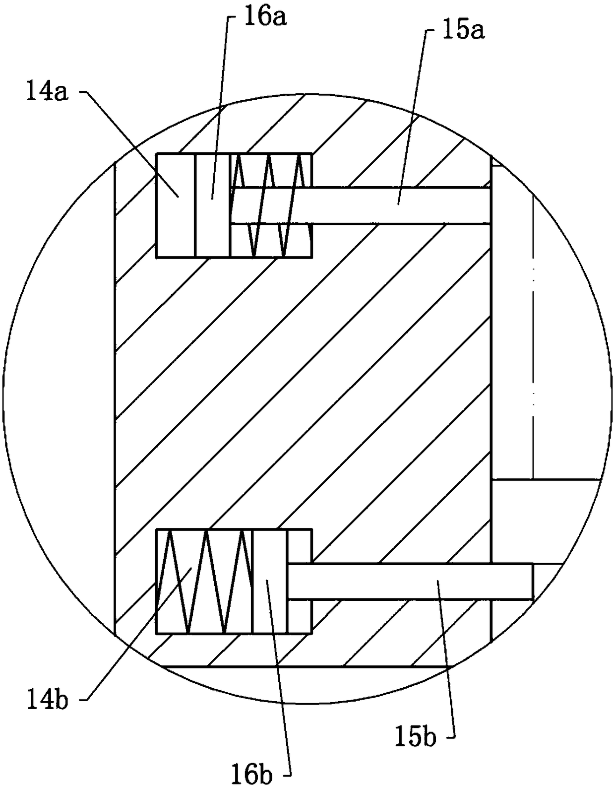
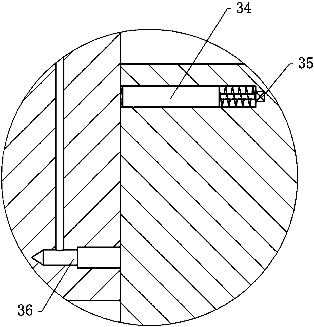
[0027] The reference signs in the drawings of the description include: seat body 10, positioning hole 11, air duct 12, throat 13, first air chamber 14a, first positioning piece 15a, first piston 16a, second air chamber 14b, second Two positioning pieces 15b, second piston 16b, mechanical arm 20, pressure chamber 21, clamping seat 30, pneumatic ejector rod 31, clamping hole 32, protrusion 33, positioning rod 34, pressure switch 35, limit hole 36.

[0028]The material transfer device for the automatic visual detection system of motor commutator in this embodiment includes a frame, a conveyor belt, a positioning part and a transfer part, and the positioning part is provided with the end of the conveyor belt to transfer the commutator to the positioning part for positioning; The part is arranged under the positioning part, so that the transfer part grabs the commutator positi...


PUM


Abstract

The invention relates to the field of automatic machining and particularly discloses a material transferring device for an automatic vision detection system of motor commutators. The material transferring device for the automatic vision detection system of the motor commutators comprises a rack, a conveying belt, a positioning part and a transferring part; the transferring part is located below the positioning part; the positioning part comprises a base body and a gas source; the middle portion of the base body is provided with a positioning hole; the positioning hole is vertically formed andpenetrates the base body; an air duct is arranged on the periphery of the positioning hole; the lower end of the air duct extends to the lower surface of the base body; the upper end of the air duct is communicated with the gas source; the lower portion of the base body is provided with a first positioning unit and a second positioning unit from top to bottom; and the first positioning unit and the second positioning unit can alternately stretch into the positioning hole to stop the commutators. The transferring part comprises a mechanical arm; one end of the mechanical arm is provided with aclamping unit capable of rising and falling; the clamping unit comprises a clamping base; the middle portion of the clamping base is provided with a clamping hole; the side wall of the clamping hole is provided with a clamping claw; and a protrusion capable of stretching into the air duct and plugging the air duct is fixed to the clamping base. According to the material transferring device for theautomatic vision detection system of the motor commutators, the commutators output on the upstream can be transferred to the automatic detection system one by one.

Description

technical field [0001] The invention relates to the field of automatic processing, in particular to a material transfer device for an automatic visual detection system of a motor commutator. Background technique [0002] In the manufacture of DC motors and AC series motors, the commutator (commutator) is a key component, and its quality level directly affects the overall quality of the motor. The appearance quality problems of the commutator due to its own material defects, processing defects or improper logistics delivery, such as bruises and other appearance defects, must be rejected as defective products. The existing mode of quality control is manual visual inspection. However, due to the many defect modes of the product, random defect locations, and inconspicuous defect characteristics, etc., there are high requirements for the judgment ability of the inspectors; in addition, if the number of products is large, manual inspection is prone to visual fatigue, and missed i...

Claims


Application Information

Patent Timeline
IPC IPC(8): B65G57/03B65G47/90
CPCB65G47/90B65G57/03
Inventor 张振军
Owner 重庆晓渝机器人有限公司
Features
  • Generate Ideas
  • Intellectual Property
  • Life Sciences
  • Materials
  • Tech Scout
  • Unparalleled Data Quality
  • Higher Quality Content
  • 60% Fewer Hallucinations
Learn More