Mini type engine combustion chamber flame barrel with air inlet flow guiding blades

A guide vane and flame tube technology, applied in the field of micro-engines, can solve the problems of poor fuel and air mixing, short flame residence time, short residence time, etc., and achieve complete combustion, increased residence time, and uniform mixing. Effect

Inactive Publication Date: 2018-06-12
NORTHWESTERN POLYTECHNICAL UNIV
View PDF3 Cites 14 Cited by
  • Summary
  • Abstract
  • Description
  • Claims
  • Application Information

AI Technical Summary

Problems solved by technology

Third, the flame residence time is short
The air velocity in the combustion chamber is very high, and the residence time of the airflow in the combustion chamber is very short, which will lead to poor mixing of fuel and air and incomplete combustion

Method used


Image

  • Mini type engine combustion chamber flame barrel with air inlet flow guiding blades
  • Mini type engine combustion chamber flame barrel with air inlet flow guiding blades
  • Mini type engine combustion chamber flame barrel with air inlet flow guiding blades

Examples


Embodiment Construction

[0019] The present invention will be further described now in conjunction with accompanying drawing:

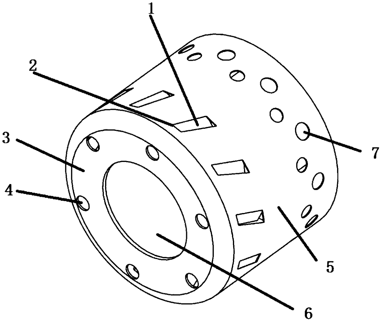
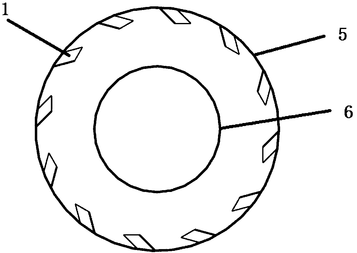
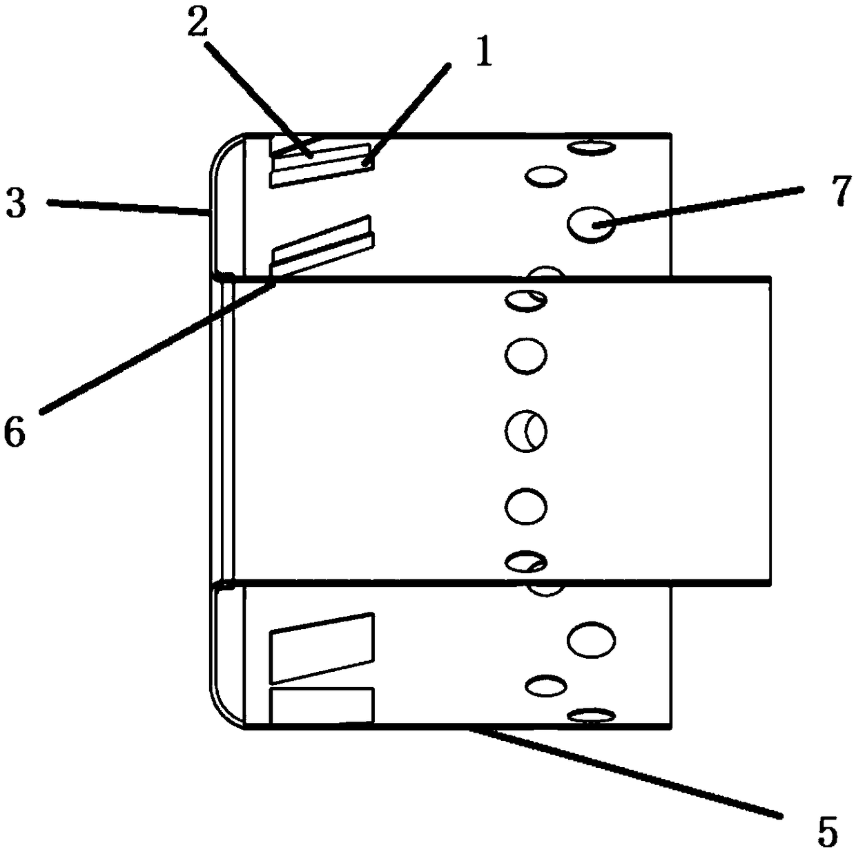
[0020] combine figure 1 , figure 2 and image 3 , the invention provides a structural design scheme of a micro-engine combustor flame tube with air inlet guide vanes. figure 1 It is a three-dimensional schematic diagram of the combustion chamber flame tube of a micro-engine with inlet guide vanes, figure 2 is a schematic diagram of the circumferential distribution of the inlet guide vanes, image 3 It is a cross-sectional view of the combustion chamber flame tube of a micro-engine with inlet guide vanes.

[0021] according to figure 1 As shown, the airflow entering the combustion chamber is divided into two parts. One part of the airflow enters the flame cylinder through the evaporation tube inlet (4) at the front end (3) of the flame cylinder. This part of the airflow is mixed with fuel to form a combustible mixture and then enters the flame cylinder for combustion. ...


PUM


Abstract

The invention provides a structural design scheme for a mini type engine combustion chamber flame barrel with air inlet flow guiding blades. The air inlet flow guiding blades are arranged at the position, close to the front end of the flame barrel, of a flame barrel shell, so that airflow entering the flame barrel through a main combustion hole has the component of velocity in the axial direction,the radial direction and the circumferential direction, a backflow area can be formed by the rotation airflow in the flame barrel, the airflow structure in the flame barrel is effectively improved, the airflow speed is reduced, and the combustion stability of a mini type engine combustion chamber is improved; and due to existence of the backflow area, the airflow turbulivity is improved, fuel oiland fresh air mixing is more sufficient, combustion is safer, and the combustion efficiency is greatly improved.

Description

technical field [0001] The invention belongs to the field of micro-engines, and in particular relates to a micro-engine combustor flame tube with air intake guide vanes. Background technique [0002] With the development needs of the market, all kinds of aircraft began to rapidly miniaturize and unmanned, including military unmanned reconnaissance drones, target drones, civilian aerial photography planes, model airplanes, etc. The appearance of these tiny aircraft has great impact on power The system puts forward new requirements. Therefore, micro-engine technology has developed rapidly in recent years. A micro engine refers to an engine with a size of centimeters or millimeters. It has the advantages of light weight, small size, high power, and high thrust-to-weight ratio. As a future high energy storage density device, it has great potential in terms of performance . [0003] The structural scheme of the combustion chamber is the key technology of micro-engine design. ...

Claims


Application Information

Patent Timeline
Patent Type & Authority Applications(China)
IPC IPC(8): F23R3/42F23R3/06
CPCF23R3/42F23R3/06
Inventor 张群张鹏王鑫海涵寇睿李承钰宋亚恒黎超超李逸飞
Owner NORTHWESTERN POLYTECHNICAL UNIV
Why Eureka
Try Eureka