Automatic debugging and correcting system and method of light-splitting path for X-ray fluorescence spectrometer

A fluorescence spectrometer and automatic debugging technology, applied in the field of X-ray fluorescence spectrometer, can solve the problems of inability to guarantee accuracy, X-ray source loss, time-consuming and labor-consuming, etc., and achieve the effect of improving debugging accuracy, high real-time performance, and reducing loss

Pending Publication Date: 2018-06-12
NCS TESTING TECH
View PDF6 Cites 9 Cited by
  • Summary
  • Abstract
  • Description
  • Claims
  • Application Information

AI Technical Summary

Problems solved by technology

[0008] A sequential wavelength dispersive X-ray fluorescence spectrometer is generally equipped with 5-10 crystals ranging from different elements to meet the measurement of various elements. Every time a crystal is debugged, it is necessary to continuously switch X-rays and remove the protective cover, which is very time-consuming and expensive. Manpower, causing loss to the X-ray source
Since the X-ray intensity collection is discrete, the experience of the debugging personnel is very high when looking for the maximum X-ray intensity, and repeated operations are required to complete the debugging, and the accuracy cannot be guaranteed.

Method used


Image

  • Automatic debugging and correcting system and method of light-splitting path for X-ray fluorescence spectrometer
  • Automatic debugging and correcting system and method of light-splitting path for X-ray fluorescence spectrometer
  • Automatic debugging and correcting system and method of light-splitting path for X-ray fluorescence spectrometer

Examples


Embodiment Construction

[0048] The present invention is further described below in conjunction with embodiment.

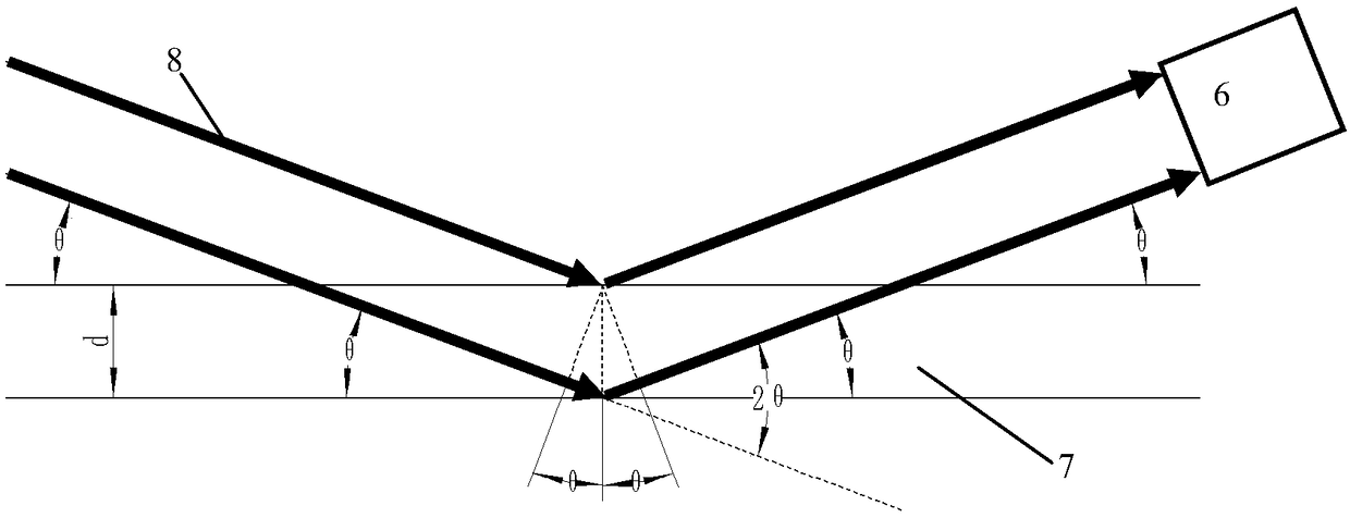
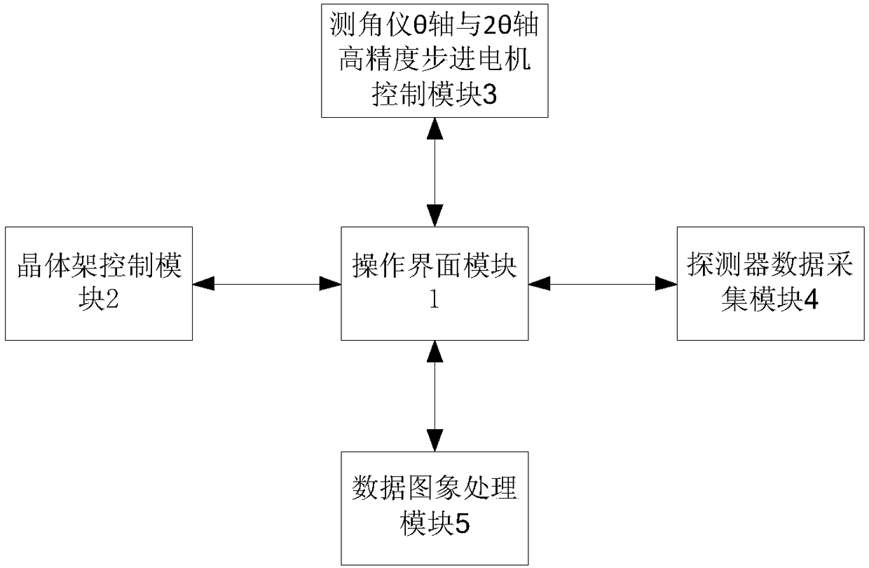
[0049] Such as figure 2 As shown, an X-ray fluorescence spectrometer automatic debugging and correction system for the spectroscopic optical path, the X-ray fluorescence spectrometer is a sequential wavelength dispersive X-ray fluorescence spectrometer, including a detector (6), a goniometer, a crystal frame and multiple spectroscopic The θ-axis and 2θ-axis of the goniometer are equipped with selected crystals and detectors respectively, and the system includes an operation interface module 1, a crystal frame control module 2, high-precision stepping motors for the θ-axis and 2θ-axis of the goniometer A control module 3 , a detector data collection module 4 and a data image processing module 5 .

[0050] The crystal frame control module 2 switches the selected crystal into the light splitting path.

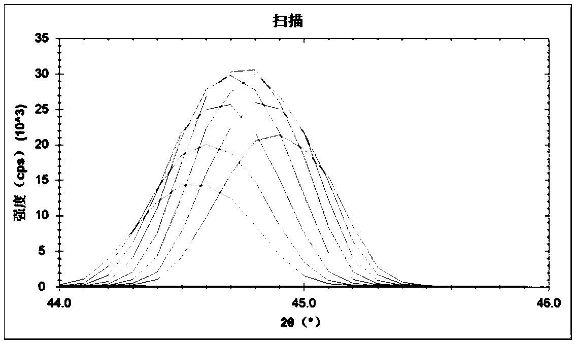
[0051] The user sets the scanning range of the goniometer θ axis and 2θ axis, the scan...


PUM


Abstract

The invention relates to an automatic debugging and correcting system and method of the light-splitting path for an X-ray fluorescence spectrometer with sequential wavelength dispersion. The automaticdebugging and correcting system comprises an operation interface module, a crystal-frame control module, a goniometer theta-axis and 2theta-axis high-accuracy stepping motor control module, a detector data acquisition module and a data image processing module. The automatic debugging and correcting system selects the spectral line of a measured element as a reference spectral line of a calibration goniometer, calculating out a crystal glancing angle and a detector emergence angle by a Bragg equation, rotating a theta axis and a 2theta axis of the goniometer to specified positions, realizing automatic adjustment of the positions of crystals and a detector by controlling a stepping motor, the crystal frame and the detector arranged at the theta axis and the 2theta axis and obtaining a crystal correction factor so as to correct the crystal glancing angle and the detector emergence angle. The automatic debugging and correcting system and method have the advantages that remote and automatic debugging for the light splitting path can be realized, debugging persons can be protected from X-ray radiation, the dependency on the debugging experience of the debugging persons can be reduced and the debugging efficiency and accuracy can be improved.

Description

technical field [0001] The invention belongs to the technical field of X-ray fluorescence spectrometers, and relates to a system and method for automatic debugging and correction of light splitting paths of sequential wavelength dispersion X-ray fluorescence spectrometers. Background technique [0002] Sequential wavelength dispersive X-ray fluorescence spectrometer is a precision instrument for precise analysis of element content. It has the characteristics of short analysis time, wide element detection range, many types of analysis samples, and no damage to analysis samples. It is widely used in petrochemical, construction, etc. Materials, metals and inorganic non-metallic materials, ceramics, identification of cultural relics, biological materials, pharmaceutical semiconductors and other fields. The splitting optical path is the core component of the wavelength dispersive fluorescence spectrometer, and plays a vital role in the performance of the instrument. The splittin...

Claims


Application Information

Patent Timeline
Patent Type & Authority Applications(China)
IPC IPC(8): G01N23/223
CPCG01N23/223
Inventor 李瑞周超宋春苗胡学强袁良经刘明博胡少成
Owner NCS TESTING TECH
Why Eureka
Try Eureka