Laser radar scanning and imaging system and measurement method thereof

A technology of scanning imaging and laser radar, which is applied in the direction of measuring devices, radio wave measurement systems, electromagnetic wave re-radiation, etc., can solve the problem of limiting the performance index and application range of MEMS type laser radar, enhancing the intensity of background light, shortening the detection distance, etc. problem, to achieve the effect of improving reliability and mass production capability, improving signal-to-noise ratio, and reducing the difficulty of production process

Pending Publication Date: 2018-06-12
苏州镭图光电科技有限公司
View PDF0 Cites 20 Cited by
  • Summary
  • Abstract
  • Description
  • Claims
  • Application Information

AI Technical Summary

Problems solved by technology

However, this method introduces new problems: due to the need to cover the entire imaging field of view, the receiving field of view of the receiving optical system is large, resulting in a strong increase in the intensity of the received background light, which seriously reduces the signal-

Method used


Image

  • Laser radar scanning and imaging system and measurement method thereof

Examples


Example Embodiment

[0025] The present invention will be described in detail below in conjunction with the embodiments shown in the drawings, but it should be noted that these embodiments are not a limitation of the present invention, and those of ordinary skill in the art make functional, method, or structural improvements based on these embodiments. Equivalent changes or substitutions fall within the protection scope of the present invention.

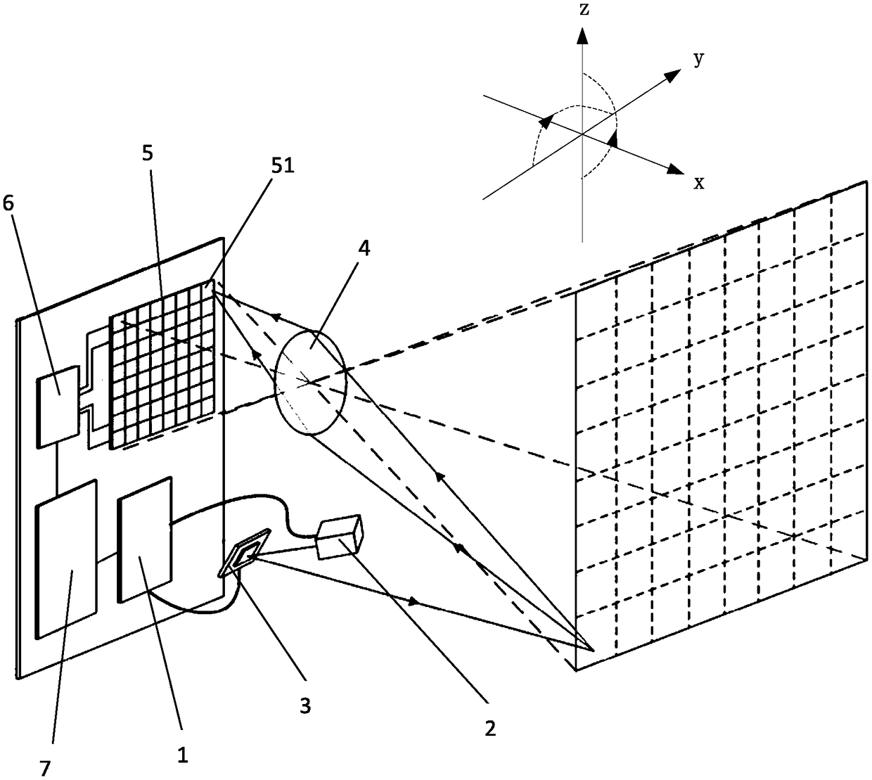
[0026] This embodiment provides a laser radar scanning imaging system (see figure 1 ), including a transmitting module (not shown), a receiving module (not shown), a data acquisition module (not shown), a main control module 1, a data transmission module, and the data transmission module is used for communication between each module Signal transmission, not shown. The transmitting module includes a laser 2 and a reflecting mirror 3, and the receiving module includes a receiving optical lens 4 and a focal plane array detector 5. The reflecting mirror 3 can ...


PUM


Abstract

The invention provides a laser radar scanning and imaging system and a measurement method thereof. The system includes a transmitting module, a receiving module, a data collecting module, a master control module and a data transmission module; the transmitting module comprises a laser device and a reflecting mirror, the receiving module includes an optical receiving lens and a focal planar array detector, and the angle of the reflecting mirror can be adjusted in two orthogonal dimensions. The method has the advantages of a scanning-type laser radar and a floodlighting-type laser radar; under aparaxial system, the transmitting optics has no need to achieve a function of receiving reflected light, and therefore a small and lightweight galvanometer can be adopted for scanning; since detectorunits arrayed on a focal plane are adopted for partitioning a view field, the corresponding view field angle of each detector unit is small, and accordingly the interference of background light is effectively reduced; by adopting the method, an imaging radar system which is lightweight, high in frame rate and wide in distance range can be achieved.

Description

technical field [0001] The invention relates to a laser radar scanning imaging system and a measuring method thereof. Background technique [0002] Lidar is a means of active detection of space information. Its basic working principle is similar to that of traditional radar: Lidar emits laser light to the detection target, and then the receiver collects the light signal reflected by the target, and determines the target by measuring the round-trip time of the transmitted signal. Due to the advantages of high coherence, directivity, and monochromaticity of laser, the laser radar system can realize long-distance and high-precision ranging functions. Extending the single-point ranging laser radar to two-dimensional through scanning or multi-element array detection can build a laser radar with imaging capabilities, so as to obtain richer regional distance information. At present, imaging laser radar has been used in autonomous driving, construction It has been applied in many o...

Claims


Application Information

Patent Timeline
IPC IPC(8): G01S17/89
CPCG01S17/89
Inventor 吴小可陈忻朱俊
Owner 苏州镭图光电科技有限公司
Why Eureka
Try Eureka