Method for judging magnetic pole polarity of motor rotor

A polarity judgment, motor rotor technology, applied in the direction of electronic commutator, motor control, generator control, etc., can solve the problem of failing to identify the polarity of the magnetic pole, and achieve the effect of fast and accurate acquisition and simple calculation method

Inactive Publication Date: 2018-06-12
SF TECH
3 Cites 9 Cited by

AI-Extracted Technical Summary

Problems solved by technology

[0004] Using the high-frequency impedance characteristics of permanent magnet synchronous motors to extract the rotor position estimation deviation Δθ input signal Adjust the input signal When approaching zero, there may actu...

Abstract

Provided is a method for judging magnetic pole polarity of a motor rotor. Pulsating high frequency voltage signals are injected into a direct axis, high frequency current response values of the directaxis and a quadrature axis are obtained; according to the response currents of the direct axis and quadrature axis, a first direct axis high frequency current corresponding to a phase shown in the description and a second direct axis high frequency current corresponding to a phase shown in the description are calculated; the magnetic pole polarity of the motor rotor is judged by comparing absolute values of the first direct axis high frequency current and second direct axis high frequency current. According to the method, only the pulsating high frequency voltage signals are injected into thedirect axis, an initial estimated value of the rotor position is obtained through calculation, and it is judged whether the initial estimated value is revised or not. The method is compared with theprior art, multiple injection voltages are not needed to acquire the corresponding parameters, the calculation method is simple, and the magnetic pole polarity of the motor rotor can be quickly and accurately obtained.

Application Domain

AC motor controlElectric motor control +6

Technology Topic

Multiple injectionPhysics +7

Image

  • Method for judging magnetic pole polarity of motor rotor
  • Method for judging magnetic pole polarity of motor rotor
  • Method for judging magnetic pole polarity of motor rotor

Examples

  • Experimental program(1)

Example Embodiment

[0010] The present application will be further described in detail below with reference to the accompanying drawings and embodiments. It should be understood that the specific embodiments described herein are only used to explain the related invention, but not to limit the invention. In addition, it should be noted that, for the convenience of description, only the parts related to the invention are shown in the drawings.
[0011] It should be noted that the embodiments in the present application and the features of the embodiments may be combined with each other in the case of no conflict. The present application will be described in detail below with reference to the accompanying drawings and in conjunction with the embodiments.
[0012] As described in the background art, the commonly used rotor magnetic pole polarity judgment method needs to be corrected based on the magnetic pole polarity estimated by the pulse vibration high-frequency signal injection method. Injecting different forms of signals works effectively, make sure they are separated by a certain time interval. It can be seen that the extraction of rotor position information in this method is too complicated, the detection period is too long, and the practicability is not high. Based on this, the embodiments of the present application provide a method for judging the polarity of rotor magnetic poles that only needs to inject a high-frequency pulse vibration signal once.
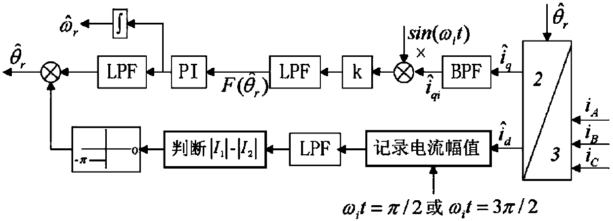
[0013] Please refer to figure 1 , inject a pulsed high-frequency voltage signal on the straight axis (d-axis) U h is the amplitude of the injected high-frequency voltage signal, ω h is the angular frequency of the injected high-frequency voltage signal.
[0014] According to the saturation characteristics of the magnetic circuit, the inductance value of the stator is different when the motor is in the paramagnetic and demagnetized directions.
[0015] i d0, the stator armature current and rotor permanent magnet flux linkage ψ m The direction is the same, and the saturation effect reduces the d-axis inductance;
[0016] i d When <0, the situation is opposite;
[0017] Using this saturation effect, the polarity of the rotor permanent magnets can be identified.
[0018] Use the intersection ( shaft) high-frequency current components to achieve rotor position estimation, while using The high-frequency current component of the shaft can determine the polarity of the tracking salient pole.
[0019]
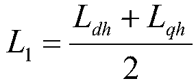
[0020] In the formula, and are the d-axis and q-axis high-frequency current response values, respectively; L dh and L qh are the dq-axis high-frequency inductances, respectively.
[0021] When sin(2Δθ)≈0, we have:
[0022]
[0023] when hour,
[0024] when hour,
[0025] When adjusting the input signal As it approaches zero, the two possible solutions are analyzed.
[0026] When , the flux linkage generated by the stator current is consistent with the positive direction of the d-axis, the magnetic circuit is saturated, the stator d-axis inductance L+ΔL becomes smaller, |I 1 |larger;
[0027] When , the flux linkage generated by the stator current is opposite to the positive direction of the d-axis, and the magnetic circuit is de-saturated.
[0028] The stator d-axis inductance L+ΔL becomes larger, |I 2 | becomes smaller; therefore |I 1 |>|I 2 |.
[0029] Initial estimate θ r No correction required.
[0030] The estimated rotor position is exactly the opposite of the actual rotor position, and the current response is as follows:
[0031] When , the flux linkage generated by the stator current is opposite to the positive direction of the d-axis, the magnetic circuit is de-saturated, the stator d-axis inductance L+ΔL becomes larger, |I 1 | become smaller;
[0032] When , the flux linkage generated by the stator current is consistent with the positive direction of the d-axis, the magnetic circuit is saturated, the stator d-axis inductance L+ΔL becomes smaller, |I 2 | becomes larger; therefore |I 1 | 2 |.
[0033] At this time, the initial estimated value θ needs to be r Corrected to θ r +π
[0034] This indicates that the initial position setting of the motor is unreasonable, the rotor position estimation enters a transient stable state, and the true positive direction of the d-axis is opposite to the assumption, in this case, the π electrical angle should be subtracted.

PUM

no PUM

Description & Claims & Application Information

We can also present the details of the Description, Claims and Application information to help users get a comprehensive understanding of the technical details of the patent, such as background art, summary of invention, brief description of drawings, description of embodiments, and other original content. On the other hand, users can also determine the specific scope of protection of the technology through the list of claims; as well as understand the changes in the life cycle of the technology with the presentation of the patent timeline. Login to view more.

Similar technology patents

Classification and recommendation of technical efficacy words

Why Eureka
Try Eureka