
Drive-by-wire hydraulic brake system and brake control method for independently controlling four-wheel pressure

An independent control and hydraulic braking technology, which is applied in the direction of braking transmission device, braking action starting device, brake, etc., can solve the problems of high price, high performance requirements of motor, and large volume of vacuum booster, so as to improve comfort , Simplify the system structure and ensure the effect of driving safety

Inactive Publication Date: 2018-06-15
JILIN UNIV
View PDF9 Cites 22 Cited by
  • Summary
  • Abstract
  • Description
  • Claims
  • Application Information

AI Technical Summary

Problems solved by technology

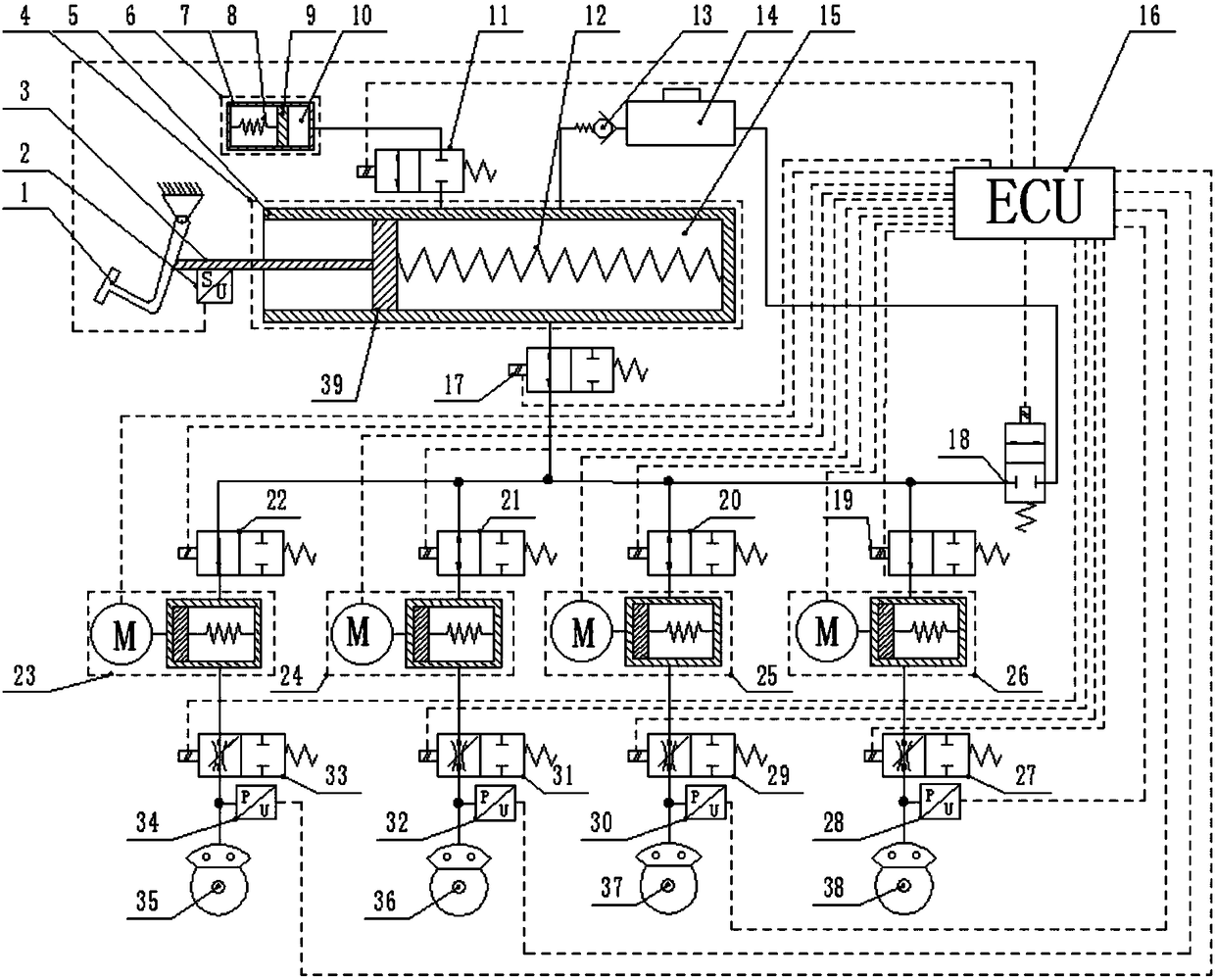
[0005] The present invention proposes a wire-controlled hydraulic braking system with four-wheel pressure independent control and its braking control method, in order to overcome the traditional braking system vacuum booster in the prior art, which is bulky, expensive, unable to realize the active braking function, and The dynamic pressure is not easy to control accurately, cannot match the current intelligent driving assistance functions such as ACC and AEB, and the existing motor-driven brake-by-wire system has relatively high requirements on motor performance. Combined with the accompanying drawings in the specification, the technical solution of the present invention as follows:

Method used


Image

  • Drive-by-wire hydraulic brake system and brake control method for independently controlling four-wheel pressure
  • Drive-by-wire hydraulic brake system and brake control method for independently controlling four-wheel pressure
  • Drive-by-wire hydraulic brake system and brake control method for independently controlling four-wheel pressure

Examples


Embodiment Construction

[0065] In order to further illustrate the technical solutions of the present invention and the beneficial effects brought by them, in conjunction with the accompanying drawings, the specific details of the present invention

[0066] The implementation is as follows:

[0067] The invention provides a wire-controlled hydraulic braking system independently controlled by four wheel pressures. The braking system consists of a brake pedal mechanism,

[0068] Composed of electronic control unit ECU, pressure control unit and brake wheel cylinder.

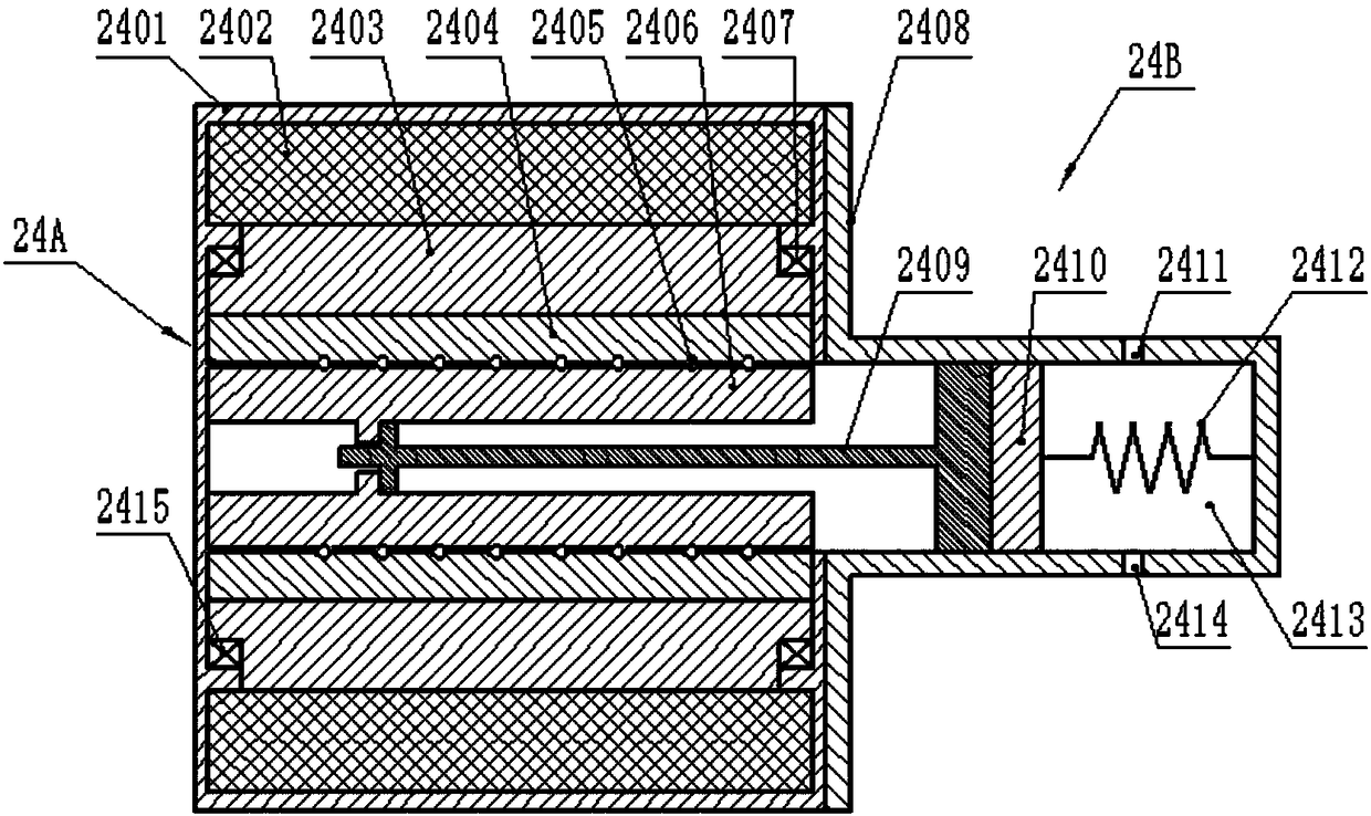
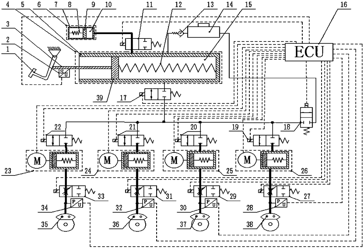
[0069] Such as figure 1 As shown, the brake pedal mechanism is composed of a brake pedal 1, a brake master cylinder 4, a pedal feeling simulator 6 and an oil storage cup 14; the brake master cylinder 4 is composed of a pedal push rod 3, a pedal displacement sensor 2 , brake master cylinder piston 39, brake master cylinder piston return spring 12, and brake master cylinder housing 5; Composed of a simulator piston 9 and a simulator sprin...


PUM


Abstract

The invention provides a drive-by-wire hydraulic brake system and brake control method for independently controlling four-wheel pressure. Four pressure control units in the system are connected with abrake main cylinder pipeline in a brake pedal mechanism through a main cylinder normally open switch electromagnetic valve, each pressure control unit is respectively composed of a normally open switch electromagnetic valve, an electronic control pressurizing unit, and a normally open linear electromagnetic valve in series sequentially; the down stream of the normally open linear electromagneticvalve is respectively with a brake wheel cylinder, pressure sensors are arranged on a pipeline where the normally open linear electromagnetic valve and the brake wheel cylinder are connected; the electromagnetic valves, the sensors and the electronic control pressurizing units are respectively in signal connection with an electronic control unit; the brake control method comprises a brake controlmethod of an effective state of electrifying and a brake control method of a failure state of outage. The four pressure control units respectively independently control the pressurization, pressure preservation or pressure reduction of the brake wheel cylinder. The drive-by-wire hydraulic brake system for independently controlling four-wheel pressure and the brake control method thereof can actively build up pressure, rapidly pressurize, accurately control pressure and has functions of failure braking and regenerative braking during vehicle braking.

Description

technical field [0001] The invention belongs to the technical field of a brake-by-wire brake system for an intelligent electric vehicle or an intelligent networked vehicle, and in particular relates to a hydraulic brake-by-wire system with four-wheel pressure independent control and a brake control method thereof. Background technique [0002] In the context of increasingly serious air pollution problems, the focus of the development of the automobile industry is gradually shifting from the field of traditional fuel vehicles to the field of new energy vehicles such as hybrid vehicles or pure electric vehicles. Under such circumstances, various companies have invested a lot of money in the design and development of new energy vehicles, and with the deepening of new energy vehicle research and development, correspondingly, the braking of new energy vehicles such as hybrid vehicles and pure electric vehicles The system puts forward new requirements. In order to achieve the ele...

Claims


Application Information

Patent Timeline
IPC IPC(8): B60T13/66B60T13/74B60T7/04B60T8/40
CPCB60T7/042B60T8/4086B60T13/66B60T13/745
Inventor 李静张振兆谷贺冲
Owner JILIN UNIV
Learn More