Anti-intertwining winding machine for spinning

A winding machine and rod winding technology, which is used in static electricity, electrical components, conveying filamentous materials, etc., can solve the problems of reducing work efficiency, troublesome work, increasing the number of winding knots, etc., to increase work efficiency and operation. Convenience and simple structure

Inactive Publication Date: 2018-06-15
SUZHOU YUDESHUI ELECTRIC TECH CO LTD
View PDF0 Cites 3 Cited by
  • Summary
  • Abstract
  • Description
  • Claims
  • Application Information

AI Technical Summary

Problems solved by technology

[0002] A winding machine is a device that winds a linear object onto a specific workpiece. Most of the wires wound by a winding machine are enamelled copper wires, enameled aluminum wires, textile wires, and electric wires for electric heating appliances. Hot wires, solder wires, wires, cables, etc.; the existing winding machines have certain disadvantages in use. First, the width and tension of the coils cannot be controlled, and they are easy to knot, which brings trouble to work and reduces work efficiency. , and it cannot guarantee that the order of the wires will not be disordered, which further increases the number of knots that occur during winding, and finally cannot eliminate the static electricity caused by friction during winding, and the safety is lacking. To a certain extent, for this reason, we propose an anti-knotting textile winding machine

Method used


Image

  • Anti-intertwining winding machine for spinning
  • Anti-intertwining winding machine for spinning
  • Anti-intertwining winding machine for spinning

Examples


Embodiment Construction

[0017] In order to make the technical means, creative features, goals and effects achieved by the present invention easy to understand, the present invention will be further described below in conjunction with specific embodiments.

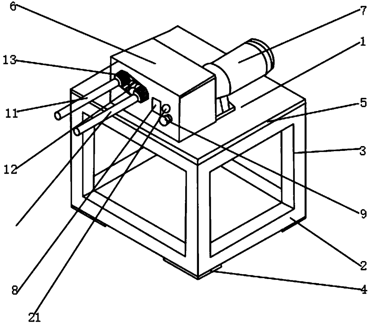
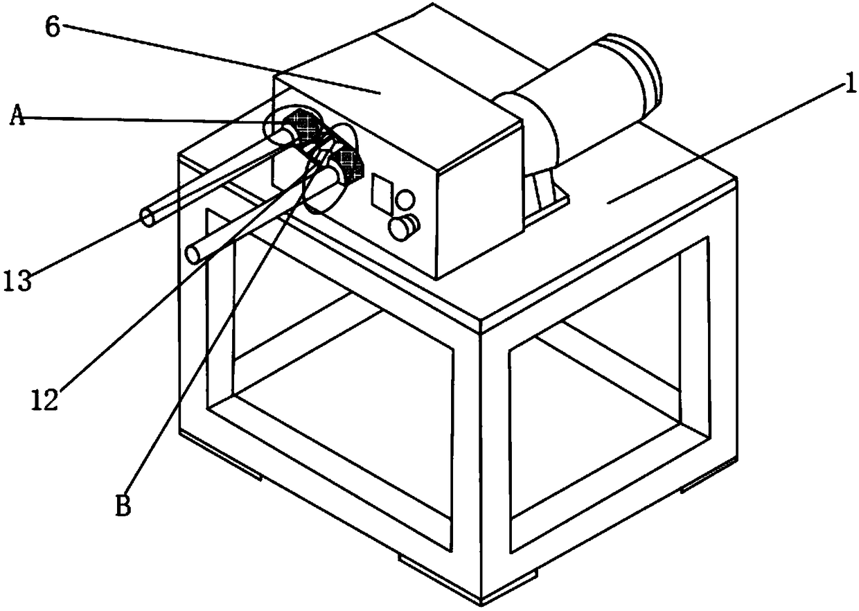
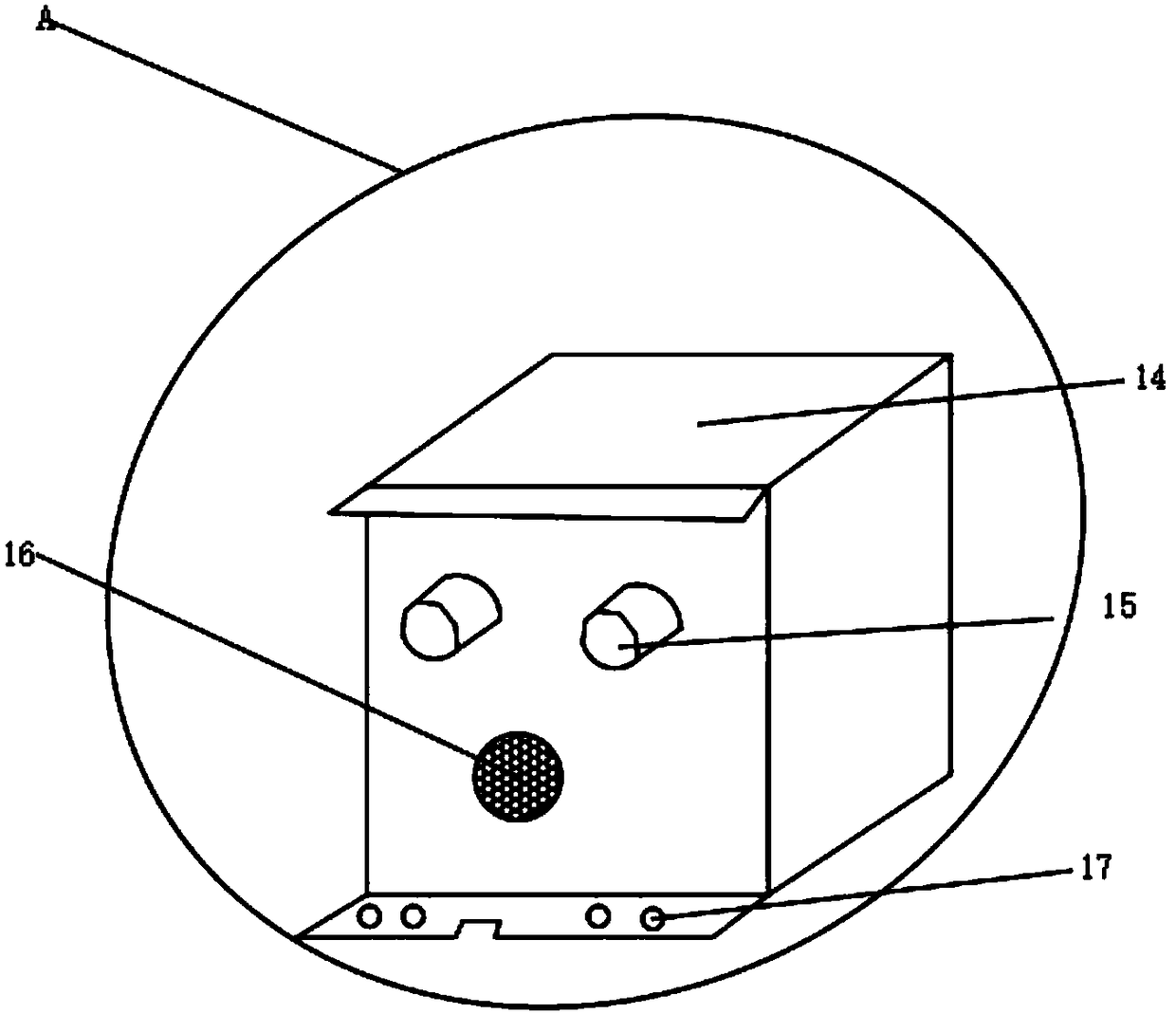
[0018] Such as Figure 1-4 As shown, an anti-knotting textile winding machine includes a main body 1 of the winding machine, a base 2 is fixedly installed on the lower end of the main body 1 of the winding machine, and a support rod 3 is fixedly installed on the upper surface of the base 2. A shim 4 is fixedly installed on the lower surface, a workbench 5 is fixedly installed on the upper end of the support rod 3, and a control cabinet 6 is fixedly installed on the upper surface of the workbench 5, and the upper surface of the workbench 5 is fixedly installed close to the position of the control cabinet 6 There is a motor 7, and the outer surface of the control cabinet 6 is provided with a display lamp 8, and one side of the display lamp 8 is fixe...


PUM


Abstract

The invention discloses an anti-intertwining winding machine for spinning. The anti-intertwining winding machine for spinning comprises a winding machine main body, wherein a base is fixedly installedat the lower end of the winding machine main body, and a support rod is fixedly installed on the upper surface of the base; a sizing block is fixedly installed on the lower surface of the base; a workbench is fixedly installed at the upper end of the support rod, and a control cabinet is fixedly installed on the upper surface of the workbench; a motor is fixedly installed at a position close to the control cabinet, of the upper surface of the workbench; and a display lamp is arranged on the outer surface of the control cabinet. According to the anti-intertwining winding machine for spinning,a second winding rod, a wire passing plate and an electrostatic eliminator are arranged, and can be cooperated with a first winding rod to control the width and tension of a wire coil, intertwining isprevented, no confusion of sequence during wire outlet can be ensured, the case of intertwining during wire winding is further prevented, and finally the static electricity brought by friction duringwire winding can be effectively eliminated, so that the safety is guaranteed, and a better use prospect is brought.

Description

technical field [0001] The invention relates to the field of winding machines, in particular to an anti-knotting textile winding machine. Background technique [0002] A winding machine is a device that winds a linear object onto a specific workpiece. Most of the wires wound by a winding machine are enamelled copper wires, enameled aluminum wires, textile wires, and electric wires for electric heating appliances. Hot wires, solder wires, wires, cables, etc.; the existing winding machines have certain disadvantages in use. First, the width and tension of the coils cannot be controlled, and they are easy to knot, which brings trouble to work and reduces work efficiency. , and it cannot guarantee that the order of the wires will not be disordered, which further increases the number of knots that occur during winding, and finally cannot eliminate the static electricity caused by friction during winding, and the safety is lacking. To a certain extent, for this reason, we propose...

Claims


Application Information

Patent Timeline
Patent Type & Authority Applications(China)
IPC IPC(8): B65H59/10H05F3/06
CPCB65H59/10B65H2701/31H05F3/06
Inventor 申俊
Owner SUZHOU YUDESHUI ELECTRIC TECH CO LTD
Why Eureka
Try Eureka