A hydraulic system automatic exhaust device and method for an electro-hydraulic brake test bench

A test bench and automatic exhaust technology, applied in fluid pressure actuation devices, fluid pressure actuation system components, fluid pressure actuation system testing, etc., can solve brake fluid corrosion, incomplete exhaust, and time-consuming air To achieve the effect of clean exhaust, avoid dirty exhaust, and precise travel

Inactive Publication Date: 2019-09-03
JILIN UNIV
View PDF7 Cites 0 Cited by
  • Summary
  • Abstract
  • Description
  • Claims
  • Application Information

AI Technical Summary

Problems solved by technology

[0004] The invention provides an automatic exhaust device and method capable of realizing the hydraulic pipeline of a brake test bench, which can be used to solve the problems of time-consuming and labor-intensive manual exhaust of the air in the brake pipeline, incomplete exhaust, and corrosion of the operator by the brake fluid. question

Method used


Image

  • A hydraulic system automatic exhaust device and method for an electro-hydraulic brake test bench
  • A hydraulic system automatic exhaust device and method for an electro-hydraulic brake test bench
  • A hydraulic system automatic exhaust device and method for an electro-hydraulic brake test bench

Examples


Embodiment Construction

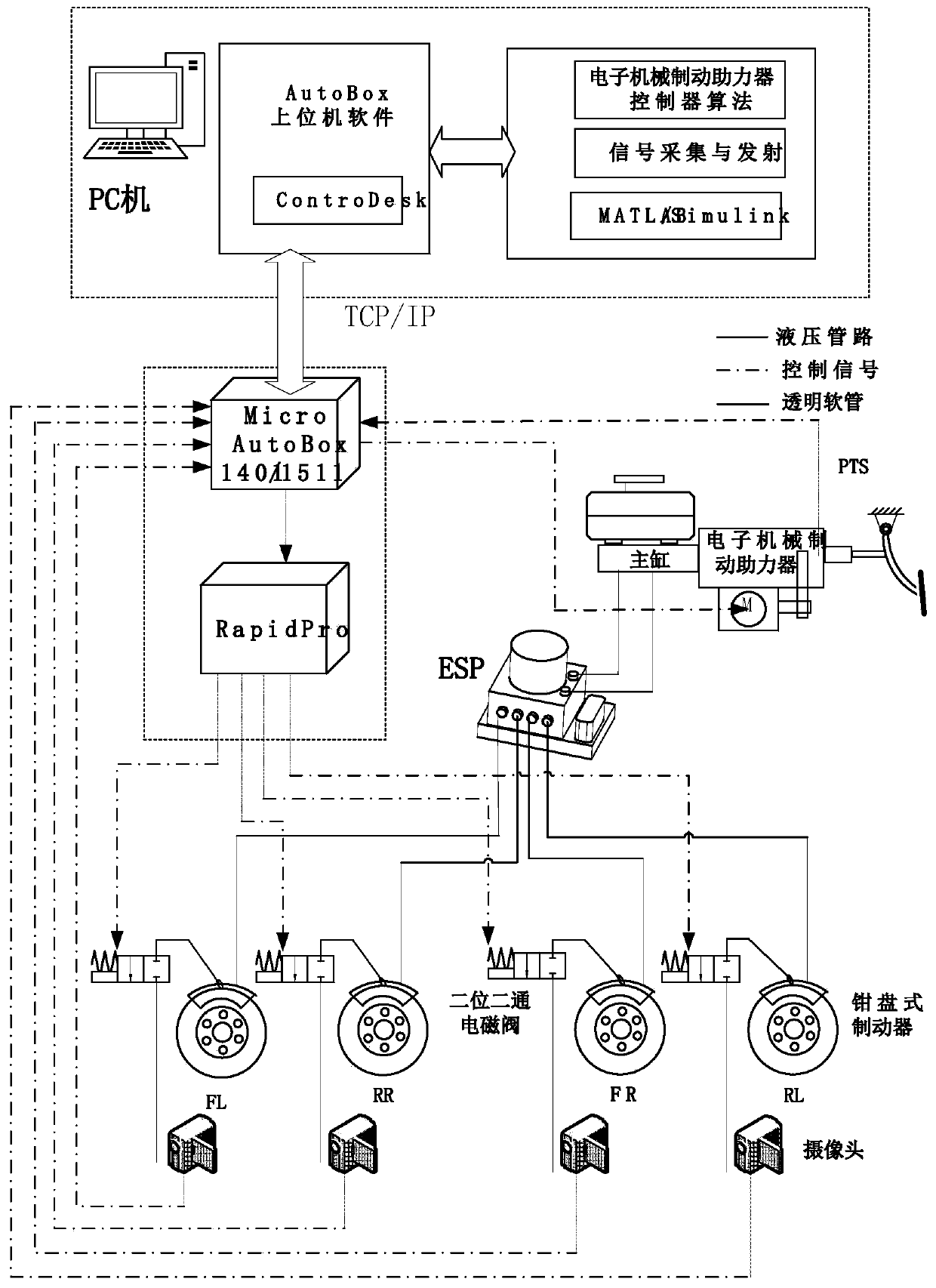
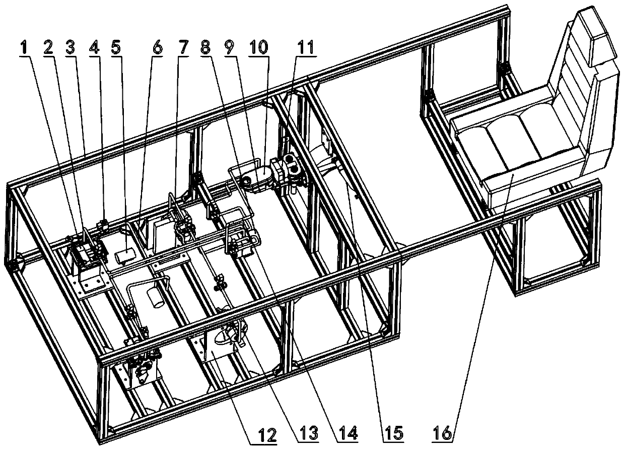
[0033] refer to figure 1 , figure 2, a hydraulic system automatic exhaust device of an electro-hydraulic brake test bench, the device includes a front brake wheel cylinder 1, a bench main body 3, a transparent hose 6, a rear brake wheel cylinder 7, and a vehicle electronic stability system 8 , brake master cylinder 9, liquid storage pot 10, electromechanical brake booster 11, support 12, brake pedal 15, adjustable seat 16, signal acquisition and launch platform, PC, two-way brake master cylinder Hydraulic pipeline 14, four two-position two-way solenoid valves 4, four caliper disc brakes 13 and four-way brake wheel cylinder hydraulic pipeline 2;

[0034] The platform main body 3 is fixed on a horizontal plane; an adjustable seat 16 is arranged at one end of the platform main body 3 ; and the support 12 is fixed on the platform main body 3 .

[0035] The electromechanical brake booster 11 is one of the control objects of the device, and the product whose publication number is...


PUM


Abstract

The invention belongs to a brake hydraulic pipeline exhausting method and particularly relates to a hydraulic system automatic exhausting device and method for an electro-hydraulic brake test bed. Thedevice comprises a front brake wheel cylinder, a test bed body, a transparent hose, a rear brake wheel cylinder, a vehicle electronic stabilization system, a brake master cylinder, a liquid storage pot, an electronic mechanical brake booster, a support, a brake pedal, an adjustable seat, a signal acquisition and transmission platform, a PC, brake master cylinder hydraulic pipelines, two-positiontwo-way solenoid valves, caliper disk brakes and brake wheel cylinder hydraulic pipelines. The device automatically judges the exhausting completion moment through recognition processing according tothe state, acquired by cameras, of brake fluid discharged from the transparent hose, controls rotation of a motor through an ECU of the mechanical brake booster to achieve operations of treadling a pedal and loosening the pedal by simulating a person. The device can be more accurate, efficient, convenient and thorough in automatic exhausting control. The problems that time and labor are wasted, exhausting is incomplete and brake fluid corrodes operators can be solved.

Description

technical field [0001] The invention belongs to a brake hydraulic pipeline exhaust method, in particular to an automatic exhaust device and method for a hydraulic system of an electro-hydraulic brake test bench. Background technique [0002] With the development of the times and the advancement of technology, the automobile braking system has developed from the initial human braking and hydraulic braking to the integrated electro-hydraulic braking system, which not only reduces the driver's operating burden and improves the driving safety of the car and it is easy to realize the integration and intelligence of the car. However, once air appears in the hydraulic brake pipeline, it will cause the brake pressure to drop or even cause the brake to fail, posing a huge safety hazard. For automobile OEMs, they usually evacuate the brake hydraulic pipeline, and then fill the brake fluid into the pipeline with high pressure to exhaust all the air. However, in the actual use of the c...

Claims


Application Information

Patent Timeline
Patent Type & Authority Patents(China)
IPC IPC(8): F15B19/00F15B21/044F15B21/02
Inventor 吴坚张浩然陈朋成陈志成刘迪
Owner JILIN UNIV
Why Eureka
Try Eureka