
Electric control box cooling structure of heat pump drying unit and heat pump drying unit

A heat pump drying and cooling structure technology, applied in the direction of heat pumps, dryers, drying gas arrangement, etc., can solve problems such as corrosion, unfavorable heat dissipation of electric control boxes, generation of static electricity, etc., to prevent excessive temperature fluctuations and prevent components from running The effect of failure

Active Publication Date: 2020-03-27
GREE ELECTRIC APPLIANCES INC
View PDF7 Cites 1 Cited by
  • Summary
  • Abstract
  • Description
  • Claims
  • Application Information

AI Technical Summary

Problems solved by technology

It is not suitable to place the electric control box of the unit in the high-temperature area or the high-humidity area, because the dry high-temperature area is not conducive to the heat dissipation of the electric control box, and it is easy to cause static electricity, while the high-humidity area is likely to cause internal components of the electric control box. Device moisture, short circuit, and even corrosion
From the perspective of cooling and safety of the electric control box, the ideal place to place the electric control box should be a dry and cold area (that is, a dry low-temperature area), that is, between the evaporator outlet and the condenser inlet, but due to the structural layout of the unit It is very inconvenient to place the electric control box in this ideal area. In addition, from the perspective of heat exchange, placing the electric control box in this area will also adversely affect the heat exchange efficiency

Method used


Image

  • Electric control box cooling structure of heat pump drying unit and heat pump drying unit

Examples


Embodiment Construction

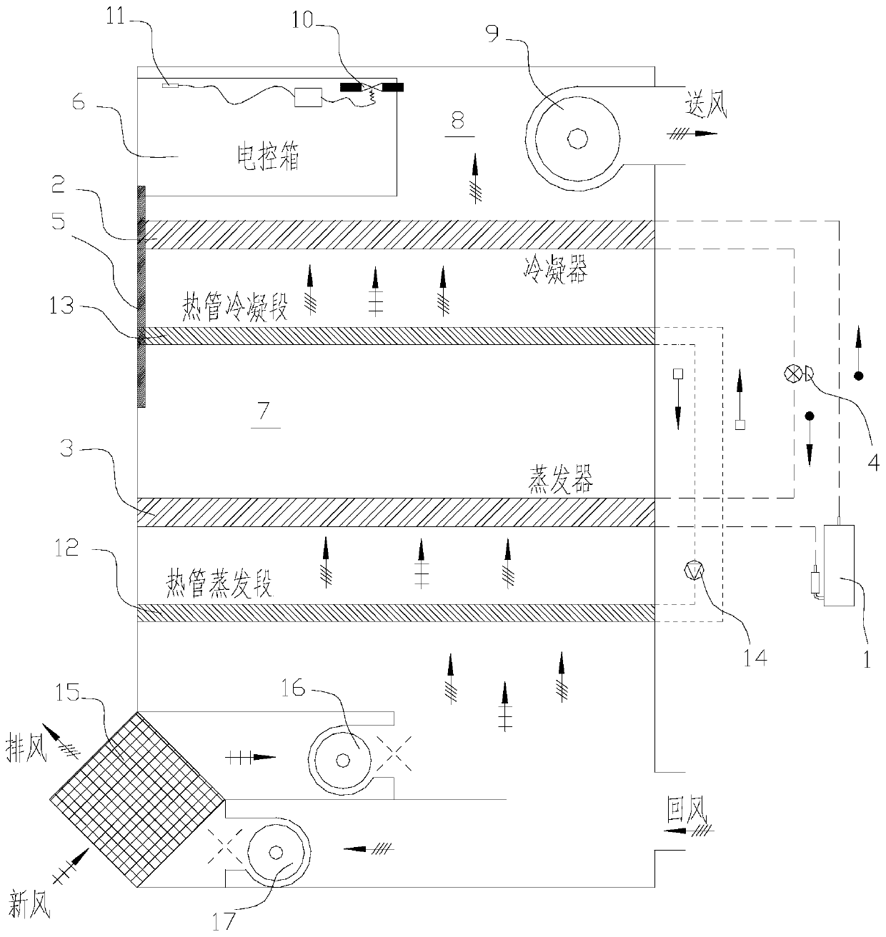
[0031] figure 1 It schematically shows a schematic diagram of the principle of the heat pump drying unit in a preferred embodiment of the present invention, and schematically shows the cooling structure of the electric control box therein.

[0032] like figure 1 As shown, the heat pump drying unit is preferably an integrated heat pump drying unit, including a heat pump system, and the heat pump system includes a compressor 1, a condenser 2, an evaporator 3 and a throttling device 4 (such as an expansion valve). During specific work, the refrigerant circulation process of the heat pump system is: compressor 1→condenser 2→throttle device 4→evaporator 3→compressor 1. Heat up. Wherein, in the air circulation direction, the evaporator 3 is arranged on the upstream side of the condenser 2 shown, so the evaporator 3 can cool and dehumidify the return air of the unit, so that it is located in the air circulation direction of the evaporator The area downstream of 3 is the dry low-te...


PUM


Abstract

The invention discloses an electric cabinet cooling structure of a heat pump drying unit. The heat pump drying unit comprises an evaporator. The evaporator is used for cooling and dehumidification onthe return air of the unit, so that the area, on the downstream part of the evaporator, in the circulation direction of air flow is the dry and low-temperature area. The electric cabinet cooling structure comprises a first air channel. The first end of the first air channel communicates with the dry and low-temperature area. The second end of the first air channel communicates with the interior ofan electric cabinet. According to the electric cabinet cooling structure, the dry and cold air in the dry and low-temperature area can be conveniently introduced into the electric cabinet so that cooling on the electric cabinet can be realized, and the operational failure, caused by too high temperature in an electric cabinet, of components can be avoided while it is not needed to arrange the electric cabinet in the dry and low-temperature area. The invention further discloses the heat pump drying unit.

Description

technical field [0001] The invention relates to the technical field of heat pump drying devices, in particular to an electric control box cooling structure of a heat pump drying unit and the heat pump drying unit. Background technique [0002] The heat pump drying device with closed circulating air duct can make full use of heat, so it has been widely recognized. However, in the prior art, the layout of the electric control box of the integral heat pump drying unit is a problem that is easily overlooked but also easily causes hidden dangers. In the integral heat pump drying unit, because the circulating airflow passes through the evaporator and the condenser in sequence, the temperature and humidity change, so there are generally dry high-temperature areas (such as the area after the condenser outlet) and high-humidity areas ( Such as the area before the evaporator inlet). It is not suitable to place the electric control box of the unit in the high-temperature area or the ...

Claims


Application Information

Patent Timeline
Patent Type & Authority Patents(China)
IPC IPC(8): F25B30/02F25B49/02F26B21/00F26B21/10
CPCF25B30/02F25B49/02F26B21/00F26B21/10
Inventor 黄玉优李欣叶强蔚
Owner GREE ELECTRIC APPLIANCES INC
Learn More