Generator on-site on-line acquisition device and monitoring system

A collection device and monitoring system technology, applied in the field of generator on-site online collection device and monitoring system, can solve the problem of inability to evaluate the damping properties of the excitation system online, affect the real-time response to power grid faults, and fail to judge the correctness of the action of the excitation limit function online and other issues to achieve the effect of facilitating offline analysis and evaluation display and improving the level of independent analysis and evaluation

Pending Publication Date: 2018-06-15
ELECTRIC POWER SCHEDULING CONTROL CENT OF GUIZHOU POWER GRID CO LTD
View PDF8 Cites 0 Cited by
  • Summary
  • Abstract
  • Description
  • Claims
  • Application Information

AI Technical Summary

Problems solved by technology

[0003] At present, the management of the generator excitation system and speed control system by the power grid is mainly through grid-related tests and technical supervision methods. The dynamic response performance of the excitation system and speed control system to changes in the power grid is mainly through offline calculation and field test measurement methods, lacking continuous monitoring. , online tracking and online evaluation technical means, so that it is impossible to judge the abnormal state of the excitation system and speed control system of a generator set online, and it is impossible to evaluate the damping properties provided by the excitation system in the grid oscillation (whether effective positive damping is provided), It is also impossible to judge the correctness of the action of the excitation limitation function online, which affects the real-time performance of power grid fault prevention and fault response

Method used


Image

  • Generator on-site on-line acquisition device and monitoring system
  • Generator on-site on-line acquisition device and monitoring system
  • Generator on-site on-line acquisition device and monitoring system

Examples


Embodiment Construction

[0022] The technical scheme of the present invention will be described in further detail below in conjunction with the accompanying drawings and specific embodiments, so that those skilled in the art can better understand the present invention and implement it, but the examples given are not intended to limit the present invention.

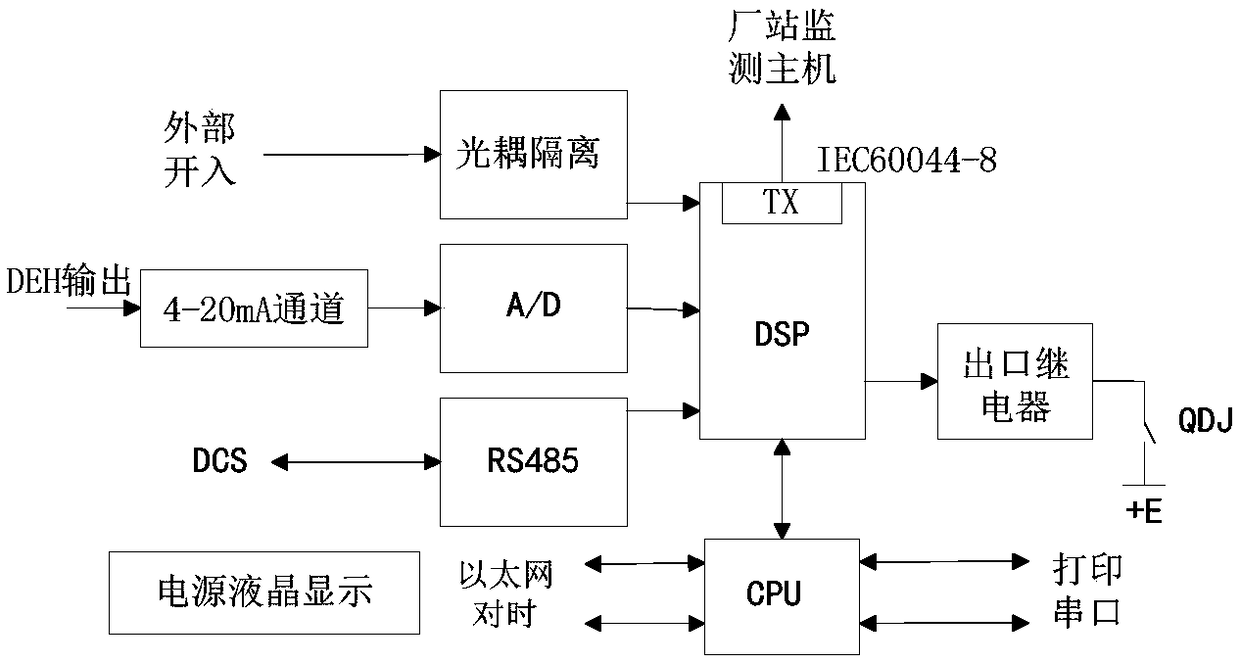
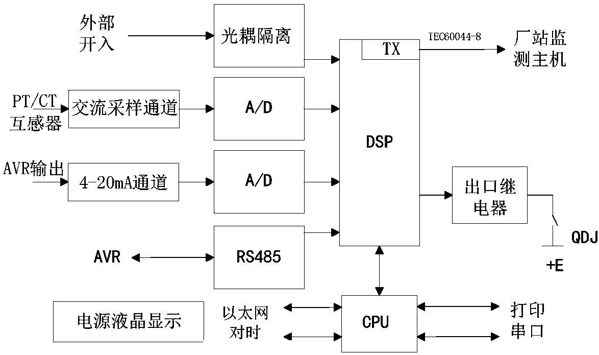
[0023] An on-site online acquisition device for generators, including a speed regulation acquisition unit arranged on the DEH screen or DCS screen side of each generator set and an excitation acquisition unit arranged on the excitation screen side of each generator, such as figure 1 As shown, the speed control acquisition unit includes a DSP processor and a 4-20mA DC flow acquisition unit, and also includes an optocoupler isolation unit and an RS485 communication unit connected to the speed control acquisition unit DSP processor, and the speed control acquisition unit DSP processor The outlet relay is connected to the positive power supply +E of th...


PUM


Abstract

The invention discloses a generator on-site on-line acquisition device and a monitoring system. A speed regulation acquisition unit arranged on a DEH screen or a DCS screen side of each generator setand an excitation acquisition unit arranged on each generator excitation screen side are included. The speed regulation acquisition unit and the excitation acquisition unit comprise DSP processors and4-20mA direct current amount acquisition units. The 4-20mA direct current amount acquisition units are connected to the DSP processors through A / D converters. The speed regulation acquisition unit comprises an optocoupler isolation unit connected to the speed regulation acquisition unit DSP processor and an RS485 communication unit. The speed regulation acquisition unit DSP processor is connectedto an operating circuit positive power supply +E through an exit relay. The excitation acquisition unit comprises an optocoupler isolation unit connected to the excitation acquisition unit DSP processor, an RS485 communication unit and an alternating current sampling unit. The alternating current sampling unit comprises a voltage transformer for collecting voltages and a current transformer for collecting currents. The excitation acquisition unit DSP processor is connected to the +E through the exit relay.

Description

technical field [0001] The invention relates to an on-site online acquisition device and a monitoring system for a generator. Background technique [0002] A large-scale power grid is generally composed of several generator sets running in parallel. The safety and control performance of the generator set and the grid operation affect and restrict each other, and the generator excitation system and speed control system are the most important links between the generator set and the grid. . Accurately mastering the mathematical models and characteristic parameters of the excitation system and speed control system of each grid-connected unit is an important part of network-related parameter management, and it is also one of the basic tasks for building a strong and smart grid. composition. [0003] At present, the management of the generator excitation system and speed control system by the power grid is mainly through grid-related tests and technical supervision methods. The ...

Claims


Application Information

Patent Timeline
Patent Type & Authority Applications(China)
IPC IPC(8): G01R31/34
CPCG01R31/343G01R31/346
Inventor 刘晓放陈根军王平陈峰王向东章熙姬源梁铃农怡陈金万会江施诗刘淑君马建伟陈胜
Owner ELECTRIC POWER SCHEDULING CONTROL CENT OF GUIZHOU POWER GRID CO LTD
Why Eureka
Try Eureka