
Auxiliary debugging method and equipment for microwave filters and storage equipment

A microwave filter and debugging method technology, which is applied to waveguide-type devices, instruments, design optimization/simulation, etc., can solve the problems of weak generalization ability, uneven distribution of matrix element values, cumbersome and other problems, so as to shorten the debugging time, The effect of improving debugging efficiency

Active Publication Date: 2018-06-15
CHINA UNIV OF GEOSCIENCES (WUHAN)
View PDF4 Cites 15 Cited by
  • Summary
  • Abstract
  • Description
  • Claims
  • Application Information

AI Technical Summary

Problems solved by technology

However, after the microwave filter is designed according to strict specifications, due to the influence of processing accuracy and assembly error, the filter often fails to meet the design indicators after production.
In order to compensate for the impact of the production process, it is often necessary to perform post-debugging on the filter. At present, the debugging basically relies on manual experience. The manual debugging process is time-consuming and cumbersome, and requires experienced debugging personnel, and the labor cost is often high.
At present, most of the forward models established by support vector regression and the reverse models established by neural networks are used to optimize the model by using the forward model established by support vector regression, but certain optimization steps are required, and the results cannot be given at one time, and Using features such as coupling
[0003] The distribution of matrix element values ​​is not uniform enough, which affects the accuracy of modeling; the reverse model established by neural network has poor generalization ability, and the features used need to be further improved

Method used


Image

  • Auxiliary debugging method and equipment for microwave filters and storage equipment
  • Auxiliary debugging method and equipment for microwave filters and storage equipment
  • Auxiliary debugging method and equipment for microwave filters and storage equipment

Examples


Embodiment Construction

[0045] In order to have a clearer understanding of the technical features, purposes and effects of the present invention, the specific implementation manners of the present invention will now be described in detail with reference to the accompanying drawings.

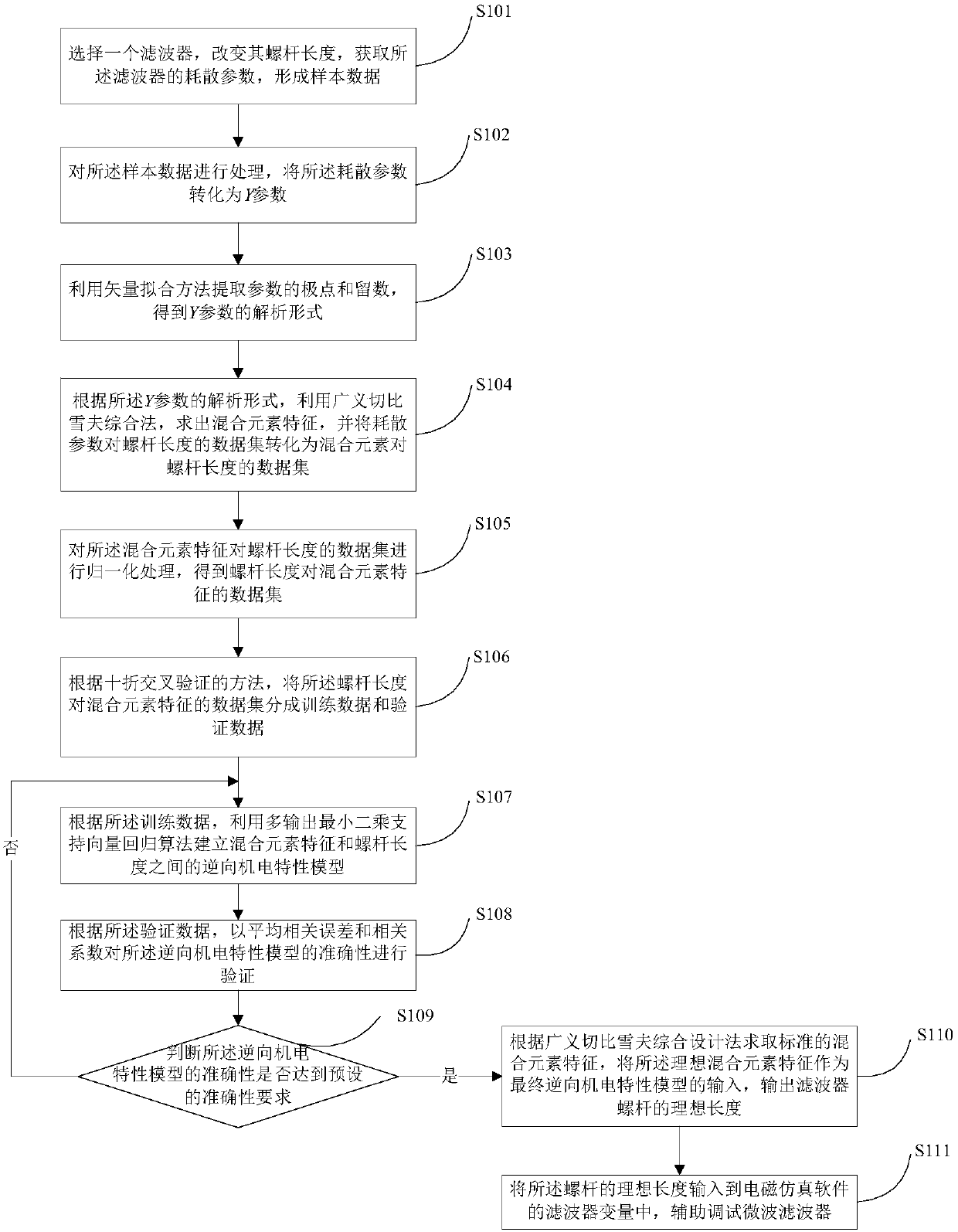
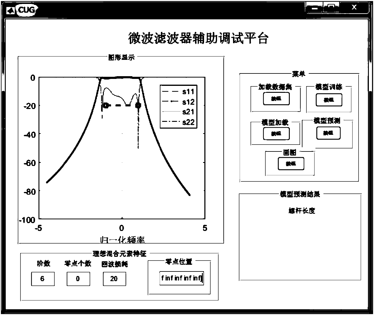
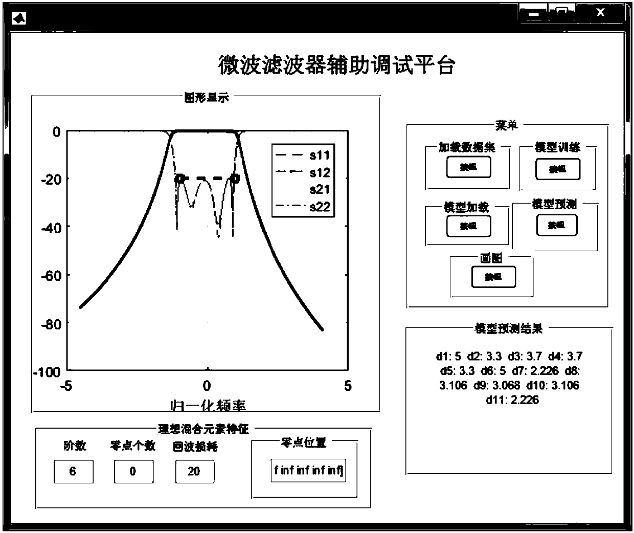
[0046] Embodiments of the present invention provide an auxiliary debugging method, device and storage device for a microwave filter with a reverse model established by mixing elements. By changing the bolt length of the microwave filter in the electromagnetic simulation software or the screw length of the actual filter, Obtain the corresponding dissipation parameter S to form a sample data set, extract the mixing elements from the dissipation parameters, and then obtain the data set Data between the characteristics of the mixing elements and the length of the screw, and then establish the characteristics of the mixing elements and the screw length by training the data set. Inverse electromechanical behavior model D betwe...


PUM


Abstract

The invention provides an auxiliary debugging method and equipment for microwave filters and storage equipment. The method comprises the following steps of: obtaining a dissipation parameter through changing a bolt length of a microwave filter in electromagnetic simulation software or a screw length of a practical filter, so as to form sample data; extracting a mixed element from the dissipation parameter; obtaining a data set Data between a mixed element feature and the screw length; training the data set to establish a reverse electromechanical characteristic model Dmodel between the mixed element feature and the screw length; and inputting an ideal mixed element designed by a generalized Chebyshev synthetic method into the model to obtain an ideal length of the screw. The auxiliary debugging method and equipment for microwave filters and the storage equipment are used for realizing an auxiliary debugging method for microwave filters. The method provided by the invention is capable of shortening the debugging time and improving the debugging efficiency.

Description

technical field [0001] The present invention relates to the technical field of microwave filters, in particular to an auxiliary debugging method, equipment and storage equipment for microwave filters. Background technique [0002] Microwave filters are essential components in wireless communication systems. Microwave filters are widely used in wireless systems. With the rapid development of wireless communication systems, more stringent index requirements are put forward for the design of microwave devices. However, microwave filters designed according to strict specifications often fail to meet the design specifications after production due to the influence of machining accuracy and assembly errors. In order to compensate for the impact of the production process, it is often necessary to perform post-commissioning on the filter. At present, the commissioning basically relies on manual experience. The process of manual commissioning is time-consuming and cumbersome, and re...

Claims


Application Information

Patent Timeline
IPC IPC(8): G06F17/50H01P1/207
CPCG06F30/20H01P1/207
Inventor 曹卫华刘璨袁艳吴敏吴生彪庄晓龙毕乐宇朱蕊
Owner CHINA UNIV OF GEOSCIENCES (WUHAN)
Learn More