Dual-axis anti-shake camera module and control method thereof
A camera module and camera module technology, applied in the field of image processing, can solve the problems of large size of the stabilization system, small effective angle range, poor image effect, etc., achieve precise control, improve accuracy and response frequency, and achieve dual image Axis stabilization effect
- Summary
- Abstract
- Description
- Claims
- Application Information
AI Technical Summary
Problems solved by technology
Method used
Image
Examples
Embodiment 1
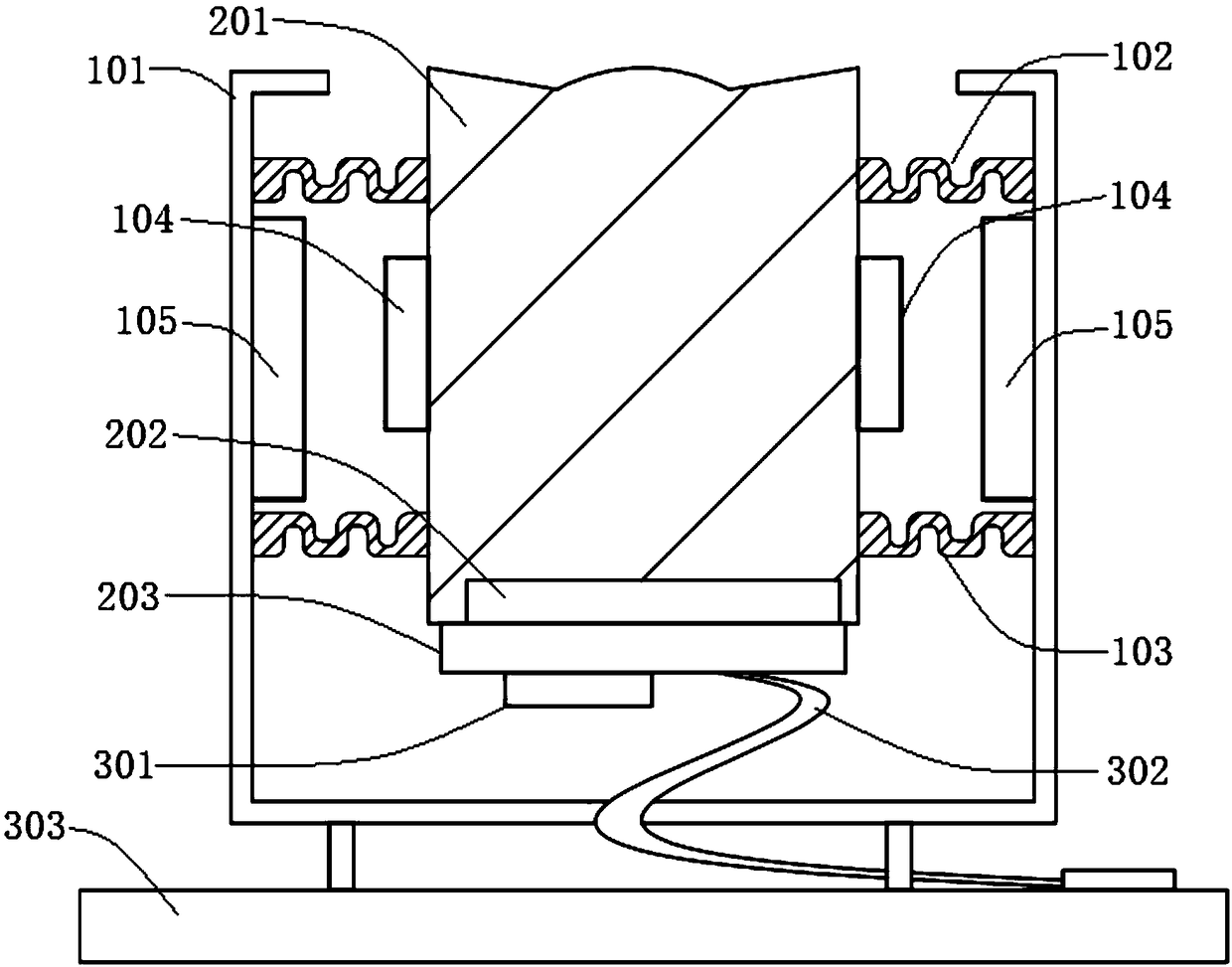
[0039] Such as figure 1 As shown, a dual-axis anti-shake camera module includes a deflection structure combination, a camera module and a stability control combination, and the deflection structure combination includes a housing 101, an upper elastic support body 102, a lower elastic support body 103, a coil 104 and The permanent magnet 105, the upper elastic support body 102 and the lower elastic support body 103 are respectively fixed in parallel in the casing 101 and supports the casing 101, and the camera module is embedded in the upper elastic support body 102 and the lower elastic support body 103, so that the camera The module is suspended in the housing 101, the coil 104 is installed on the outer wall of the camera module, and the permanent magnet 105 is installed on the inner wall of the housing 101 corresponding to the position of the coil 104; The bottom is connected to the stability control combination.
[0040]In this embodiment, each component can be divided int...
Embodiment 2
[0042] In this embodiment, on the basis of Embodiment 1, the camera module includes a lens 201, an image sensor 202 and a first circuit board 203, the coil 104 is mounted on the outer wall of the lens 201, and the image sensor 202 is mounted on The bottom of the lens 201 ; the first circuit board 203 is located under the lens 201 and is close to the image sensor 202 . The image sensor 202 is mounted on the first circuit board 203 for receiving image information, and performs biaxial offset movement together with the lens 201, so that the overall stable control of the image sensor 202 and the lens 201 can be implemented, avoiding separately controlling the lens 201 or The image sensor 202 has the disadvantages of lack of precision and image distortion.
Embodiment 3
[0044] In this embodiment, on the basis of Embodiment 2, the stability control combination includes an inertial sensor 301, a flexible connection circuit 302 and a second circuit board 303, the inertial sensor 301 is fixedly connected to the first circuit board 203, and the The first circuit board 203 is electrically connected to the second circuit board 303 through the flexible connection circuit 302 .
[0045] In this embodiment, the stability control combination includes an inertial sensor 301, a flexible connection circuit 302, and a second circuit board 303. The inertial sensor 301 is fixedly connected to the camera module, and can be assembled on the first circuit board 203 or on a flexible circuit board 303. On the connection circuit 302, the accuracy and response frequency of motion feedback are improved, thereby improving the performance of stable images; the flexible connection circuit 302 transmits the data signals of the inertial sensor 301 and the image sensor 202 ...
PUM
 Abstract
Description
Claims
Application Information
 - R&D
- Intellectual Property
- Life Sciences
- Materials
- Tech Scout
- Unparalleled Data Quality
- Higher Quality Content
- 60% Fewer Hallucinations
Browse by: Latest US Patents, China's latest patents, Technical Efficacy Thesaurus, Application Domain, Technology Topic, Popular Technical Reports.
© 2025 PatSnap. All rights reserved.Legal|Privacy policy|Modern Slavery Act Transparency Statement|Sitemap|About US| Contact US: help@patsnap.com


