
Chain welding machine used for butt welding of chain link resistors

A technology of resistance butt welding and welding machines, which is applied in the direction of resistance welding equipment, welding equipment, metal chains, etc., can solve the problems of complex modification and achieve the effect of short total process time

Active Publication Date: 2018-06-19
WAFIOS AKTIENGES
View PDF8 Cites 13 Cited by
  • Summary
  • Abstract
  • Description
  • Claims
  • Application Information

AI Technical Summary

Problems solved by technology

However, retrofitting to another process is complicated, for example when changing the chain link material or when changing to another geometry

Method used


Image

  • Chain welding machine used for butt welding of chain link resistors
  • Chain welding machine used for butt welding of chain link resistors
  • Chain welding machine used for butt welding of chain link resistors

Examples


Embodiment Construction

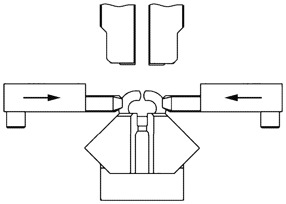
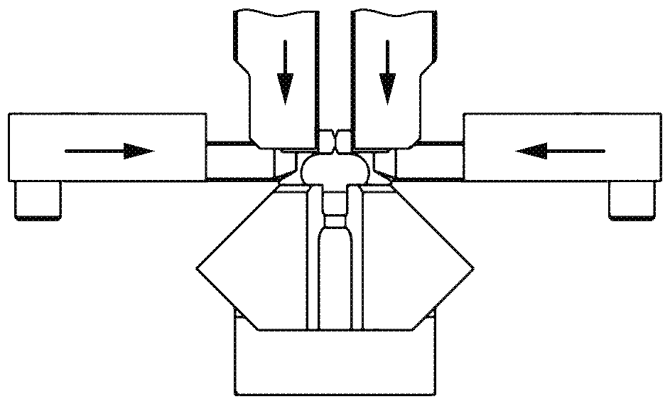
[0043] exist figure 1 An oblique perspective view of a chain welding machine 100 according to an embodiment for extruding butt welding chain links is schematically shown in . The chain welding machine has a frame 110 , which consists in part of welded steel sheets and has an extremely bending-rigid and load-bearing configuration. Inside the machine frame, a control shaft accessible from the rear side is supported with a horizontal axis of rotation. The mechanical control shaft is driven by means of an asynchronous servomotor, which enables a force transmission relative to the control shaft via a belt drive or chain drive or a gear mechanism. Starting from the control shaft, a large number of kinematic functions are controlled over time via the cam disc and the eccentric, but the forging process is not controlled. Path reduction and force increase are achieved by means of appropriately designed levers and deflections. The forces required for the respective functions are appl...


PUM


Abstract

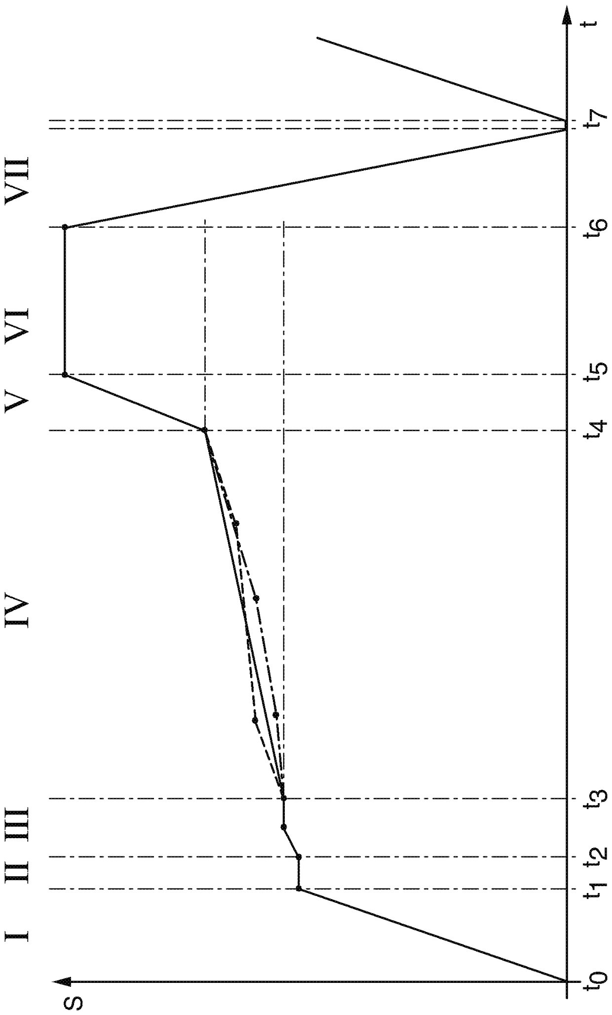
The present invention relates to a chain welding machine used for the butt welding of the chain link resistors with the help of the extrusion butting welding. The chain welding machine has a rack, a control shaft used for controlling the motion function of the chain welding machine in time, a chain conveying device used for conveying the chain links that are not welded to the welding positions andexporting the welded chain links from the welding position after the welding operation, an electrode assembly having at least one pair of electrodes that can be provided to the to-be-welded chain link end parts and used for conveying a welding current and two block forging steel racks supporting movably, wherein the block forging steel racks are arranged at the relative sides of the welding positions and are used for bearing the block forging steels used for transmitting the block forging forces and the block forging paths to the chain links at the sides facing each other. A block forging system acting on the block forging steel racks and used for providing the block forging forces and the block forging paths according to the specified block forging progress is designed to programme a block forging curve irrelevant with the control shaft by utilizing the definable correlation between the block forging paths and a time progress and can be programmed freely.

Description

technical field [0001] The invention relates to a chain welding machine according to the preamble of claim 1 for resistance butt welding of chain links. Background technique [0002] Chains with chain links bent from wire elements are currently manufactured on a large scale by means of special automated machine tools. In the case of manufacture, the chain link is bent from a first straight wire piece of suitable length. The chain links that have been bent but are still open at one point are then connected to other chain links to form a chain bundle. Subsequently, the bent, still open chain links of the chain bundle are welded to form closed chain links by means of a suitable resistance butt welding method. In this case, a cohesive connection of the free ends of the bent chain links is produced. The resistance butt welding method can be automated by means of a special chain welding machine. [0003] Resistance butt welding methods used in the context of chain manufacturin...

Claims


Application Information

Patent Timeline
Patent Type & Authority Applications(China)
IPC IPC(8): B23K11/02B23K37/047B23K11/31
CPCB23K11/02B23K11/318B23K37/047B21L3/02
Inventor J.劳舍尔F.斯蒂芬P.哈恩
Owner WAFIOS AKTIENGES
Learn More