
Connecting plate type barrier-free bus door driven by rod-free cylinder

A rodless cylinder and connecting plate technology, which is applied to the arrangement, transportation and packaging of vehicle components, pedals or ladders, etc., can solve the difficulties of independently boarding the bus, stuck or inaccurate positions, and slow expansion and contraction speed of the guide plate, etc. problems, to achieve the effect of easy integration or modification, less pollution and jamming, and avoiding stagnation

Inactive Publication Date: 2018-06-19
NANJING INST OF RAILWAY TECH
View PDF6 Cites 3 Cited by
  • Summary
  • Abstract
  • Description
  • Claims
  • Application Information

AI Technical Summary

Problems solved by technology

However, considering factors such as safe operation, usually there is still a certain span between the bus door and the platform, which is not a big problem for ordinary passengers, but for the disabled or vulnerable people traveling with baby carriages, independent boarding Getting on the bus is still difficult
[0003] At present, the motor drive is added to the structure based on the forward and reverse driving of the motor to drive the ball screw to push the guide plate to expand and contract. The expansion and contraction speed of the guide plate is relatively slow, and the screw cannot be self-locked. Pneumatic barrier-free bus doors with pull-out slopes, such as "Pneumatic Pull-type Barrier-free Bus Doors with Slopes" (patent application number 201610200804.5), use the pneumatic system to drive the slopes to expand and contract, and roll on both sides of the slopes The mechanism is installed on the rails on both sides to slide. The design and installation of the rolling mechanism is time-consuming and labor-intensive, and the cost is high. Long-term use is prone to jamming due to impurities and particle pollution, and poor operation

Method used


Image

  • Connecting plate type barrier-free bus door driven by rod-free cylinder
  • Connecting plate type barrier-free bus door driven by rod-free cylinder

Examples


Embodiment Construction

[0023] Embodiments of the present invention will be described in further detail below in conjunction with the accompanying drawings.

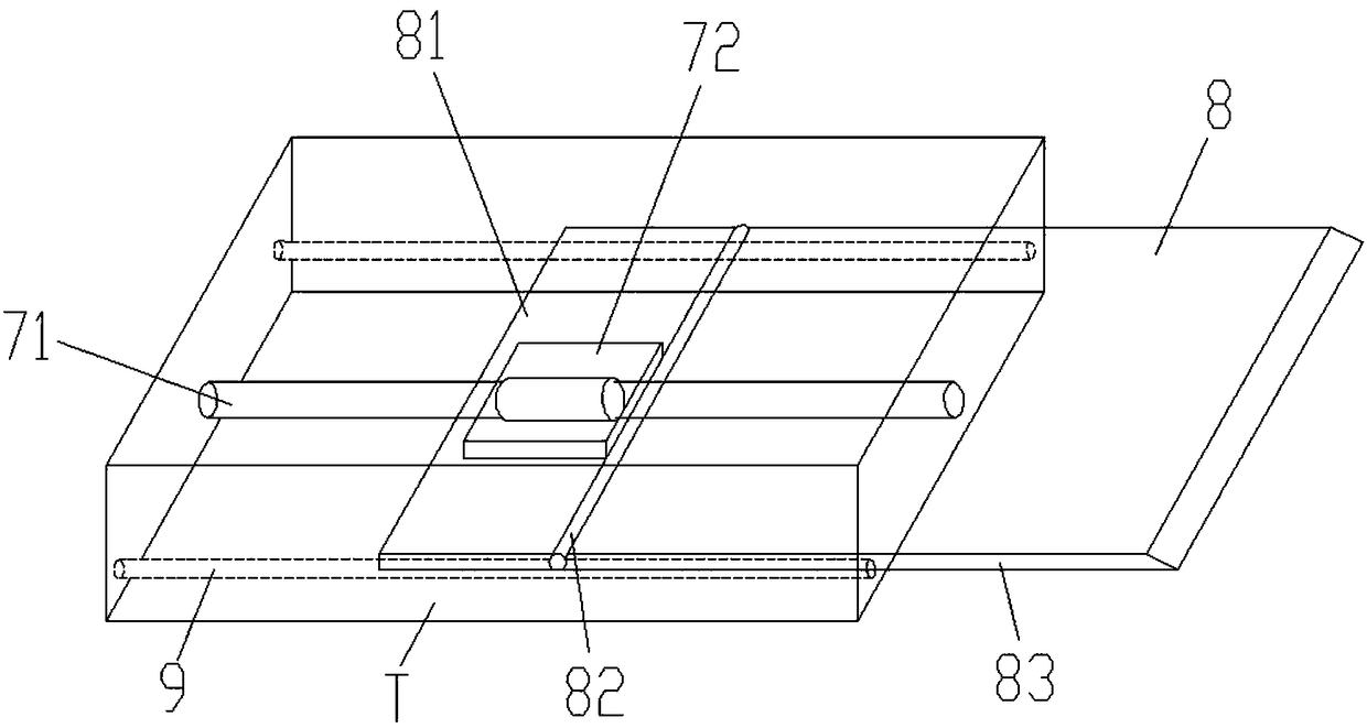
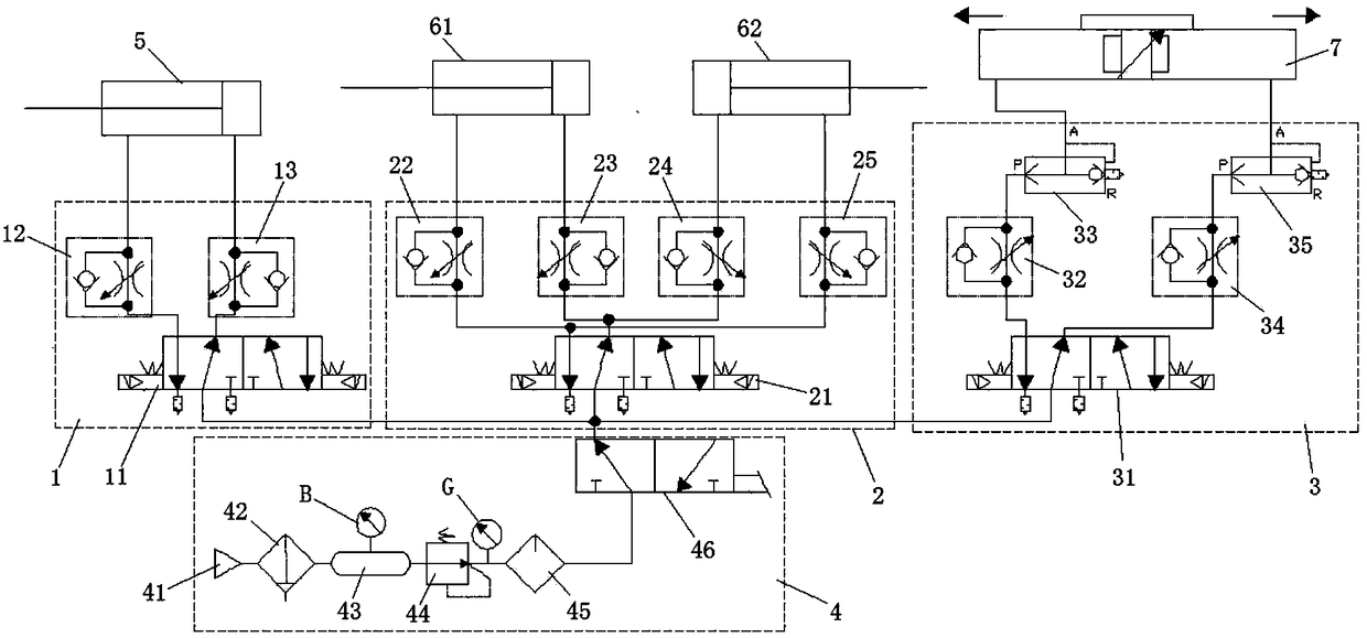
[0024] The reference signs are: gas tank pressure gauge B, air supply pressure gauge G, connecting plate installation box T, front door air control system 1, front door electromagnetic reversing valve 11, front door first one-way throttle valve 12, front door The second one-way throttle valve 13, the rear door air control system 2, the rear door electromagnetic reversing valve 21, the first one-way throttle valve 22 of the left side of the rear door, the second one-way throttle valve 23 of the left side of the rear door, the right side of the rear door Side door first one-way throttle valve 24, rear door right side door second one-way throttle valve 25, connecting plate air control system 3, connecting plate electromagnetic reversing valve 31, connecting plate left one-way throttle valve 32. The left quick exhaust valve 33 of the connecting pla...


PUM


Abstract

The invention discloses a connecting plate type barrier-free bus door driven by a rod-free cylinder. The connecting plate type barrier-free bus door driven by a rod free cylinder comprises a connecting plate set, an air general control system, a connecting plate rod-free cylinder, a connecting plate rod-free cylinder, a bus front door cylinder and a bus rear door cylinder, wherein the connecting plate set is arranged on the lower portion of a bus rear door floor. The air general control system comprises a front door air control system, a rear door air control system, a connecting plate air control system and an air source general road system, wherein the air source general road system is used for providing pressure source for the front door air control system, rear door air control systemand connecting plate air control system. Two smooth supporting rods are arranged on the lower portion of the bus rear door floor, wherein the two smooth supporting rods are fixedly arranged in parallel, and the two smooth supporting rods are used for supporting the connecting plate set and providing guiding support for the sliding of the connecting plate set. The connecting plate rod-free cylinderis arranged between the two smooth supporting rods. The connecting plate rod-free cylinder comprises a rod-free cylinder guiding rod and a rod-free cylinder sliding platform, wherein the rod-free cylinder guiding rod is fixedly arranged, and the rod-free cylinder sliding platform works on the rod-free cylinder guiding rod to drive the connecting plate set to extend from the bus rear door floor toconnect with a bus platform to achieve the barrier-free accessibility.

Description

technical field [0001] The invention relates to the technical field of bus door design, in particular to a cylinder-driven barrier-free bus door, in particular to a rodless cylinder-driven connecting plate barrier-free bus door. Background technique [0002] Now the buses operating in the city have increased the door width, reduced the height between the car body and the ground, increased the height of the platform, and reduced the height difference between the vehicle ground and the platform. However, considering factors such as safe operation, usually there is still a certain span between the bus door and the platform, which is not a big problem for ordinary passengers, but for the disabled or vulnerable people traveling with baby carriages, independent boarding It is still difficult to get on the bus. [0003] At present, the motor drive is added to the structure based on the forward and reverse driving of the motor to drive the ball screw to push the guide plate to expa...

Claims


Application Information

Patent Timeline
Patent Type & Authority Applications(China)
IPC IPC(8): B60R3/02
CPCB60R3/02
Inventor 陈辉王磊吴海超
Owner NANJING INST OF RAILWAY TECH
Learn More