
A kind of anti-backflow device and engine egr system

An anti-backflow, engine technology, applied in the direction of charging system, engine components, machines/engines, etc., can solve the problems of difficult to achieve EGR, impossible to achieve EGR, exhaust gas backflow, etc., to prevent backflow, promote positive flow, Achieve the effect of exhaust gas recirculation

Active Publication Date: 2020-06-02
WEICHAI POWER CO LTD
View PDF4 Cites 0 Cited by
  • Summary
  • Abstract
  • Description
  • Claims
  • Application Information

AI Technical Summary

Problems solved by technology

[0004] However, due to the inherent characteristics of the engine and the supercharger, when the engine is at low speed and high torque, the intake pressure of the engine is higher than the pressure in front of the turbine, and the gas in the engine intake pipe will even flow back to the turbine through the EGR pipeline. front pipe, difficult to achieve EGR
In addition, the layout of the existing EGR system is basically that the EGR pipeline includes more than two EGR air intake pipes, one end of each EGR air intake pipe is connected to one or more engine cylinders, and the other end is connected to the main EGR pipeline after confluence. , the problem with this arrangement is that when one of the EGR intake pipes performs exhaust gas recirculation, the exhaust gas will flow back into other EGR intake pipes, resulting in a decrease in the EGR rate
[0006] To solve the problem that the EGR rate of the engine EGR system is low or even unable to realize EGR has become an urgent problem to be solved by those skilled in the art

Method used


Image

  • A kind of anti-backflow device and engine egr system
  • A kind of anti-backflow device and engine egr system
  • A kind of anti-backflow device and engine egr system

Examples


Embodiment Construction

[0040] The core of the present invention is to provide an anti-backflow device, which can prevent gas backflow in the pipeline.

[0041] The invention also provides an engine EGR system including the anti-backflow device, which can prevent gas from flowing back in the EGR pipeline, realize exhaust gas recirculation under low-speed and high-torque conditions of the engine, and increase EGR rate under other conditions.

[0042] The present invention also provides another engine EGR system comprising the anti-backflow device, which can prevent the gas from flowing back in the EGR air intake pipe, realize exhaust gas recirculation under low-speed and high-torque conditions of the engine, and increase the EGR rate under other conditions .

[0043]The following will clearly and completely describe the technical solutions in the embodiments of the present invention with reference to the accompanying drawings in the embodiments of the present invention. Obviously, the described embodi...


PUM


Abstract

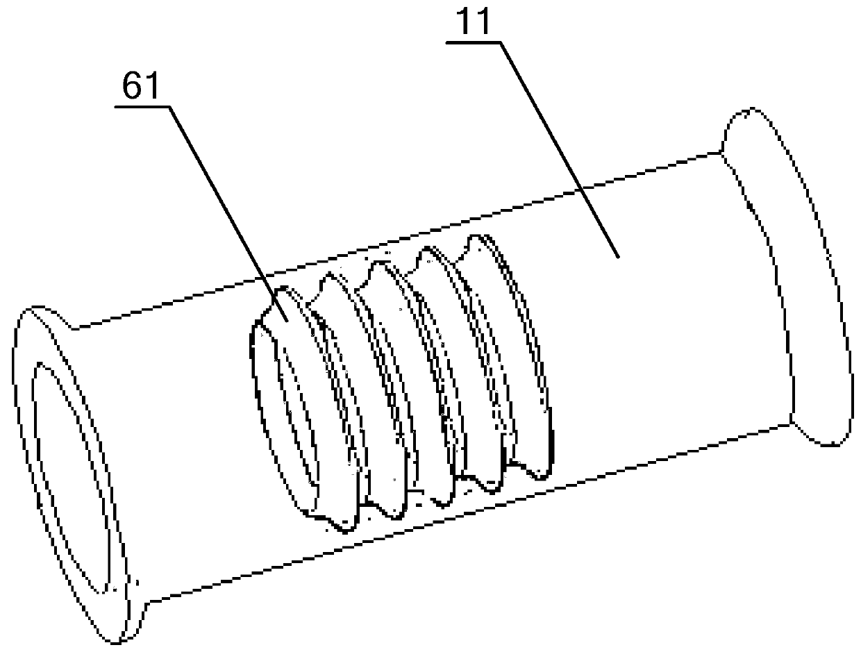
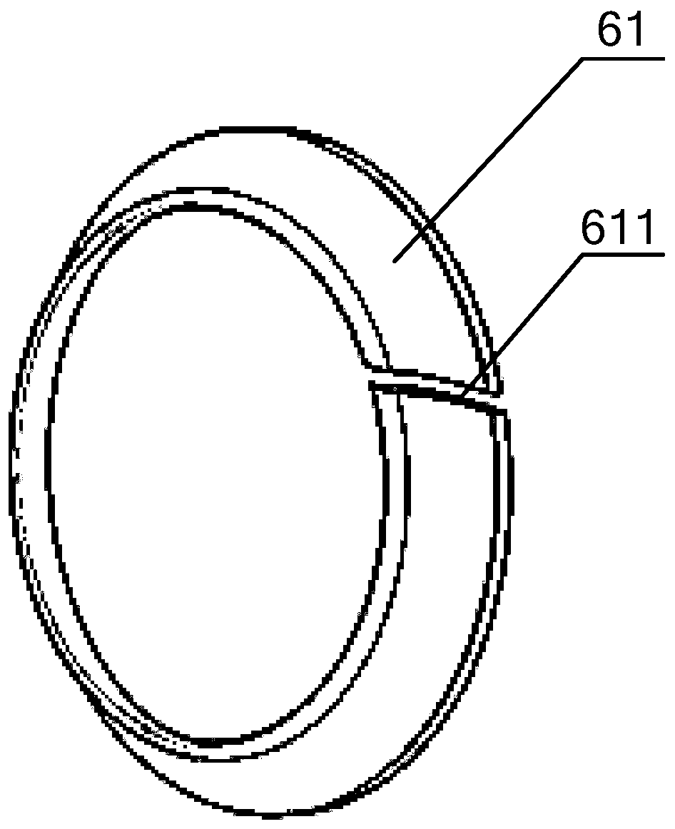
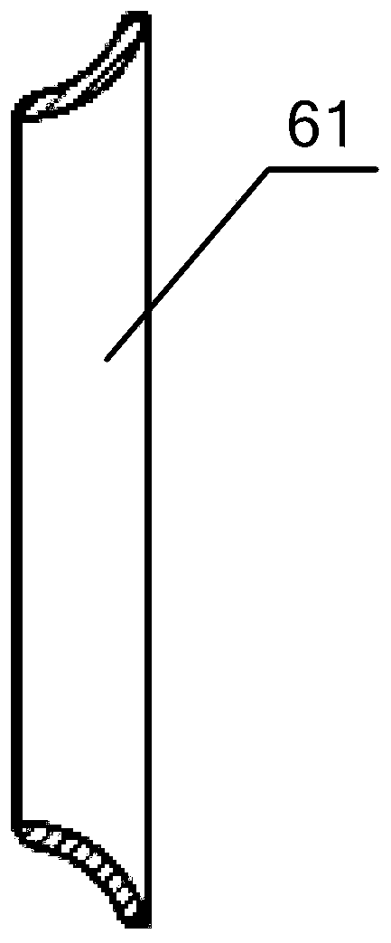
The invention discloses a backflow preventing device and an engine EGR (Exhaust Gas Recirculation) system. The backflow preventing device comprises one or a plurality of gradual-reducing rings which are arranged in a pipeline, wherein the outer edges of the gradual-reducing rings are connected to the inner wall of the pipeline; the plurality of gradual-reducing rings are arranged along an axis ofthe pipeline; the flowing sections of the gradual-reducing rings are gradually reduced in the axial direction of the gradual-reducing rings. According to the backflow preventing device, throttle lossat different degree can be produced based on different flowing directions in a pipe; when air flows in the direction (forward direction) that the flowing section area of the gradual-reducing rings decreases, the throttle loss is small; when then air flows in the direction (opposite direction) that the flowing section area of the gradual-reducing rings, the throttle loss increases. Therefore, the gradual-reducing rings are capable of inhibiting opposite flowing and promoting forward flowing in case that air reciprocates in the pipe, and as a result, air is prevented from backflow in the pipeline.

Description

technical field [0001] The invention relates to the technical field of engine exhaust gas recirculation, in particular to an anti-backflow device. It also relates to an engine EGR system including the anti-backflow device. Background technique [0002] EGR (abbreviation for Exhaust Gas Recirculation in English, Chinese name is Exhaust Gas Recirculation) technology is a technology that reintroduces part of the exhaust gas after engine combustion into the engine cylinder for reburning. This technology reduces nitrogen oxides (NOx) in exhaust gases and improves fuel economy. [0003] Existing engine EGR system mainly comprises engine, supercharger, EGR cooler and EGR pipeline, and the two ends of EGR pipeline are respectively communicated with the turbine front pipeline of supercharger and engine intake pipeline, and EGR cooler is arranged on In the EGR pipeline. There are exhaust pulses in the engine. During a complete engine cycle, each cylinder of the engine completes the...

Claims


Application Information

Patent Timeline
Patent Type & Authority Patents(China)
IPC IPC(8): F02M26/13
CPCF02M26/13
Inventor 李卫刘俊龙李志杰潘洁王作峰刘春涛康天钦
Owner WEICHAI POWER CO LTD
Learn More