Optical fiber micro-displacement sensing and calibrating device and method

A correction device and micro-displacement technology, applied in the field of displacement sensing, can solve the problems of difficult detection and correction of small optical fiber deviations, and achieve excellent sensing and correction effects, wide application range, and low cost

Inactive Publication Date: 2018-06-19
安徽三汇电子科技有限公司
View PDF5 Cites 4 Cited by
  • Summary
  • Abstract
  • Description
  • Claims
  • Application Information

AI Technical Summary

Problems solved by technology

[0005] The technical problem mainly solved by the present invention is to provide an optical fiber micro-displacement sensing and correction device and method, which can detect the change of the position of the optical fiber with high sensitivity, long distance, and real-time, so as to perform correction and enhance the controllability of the optical fiber. Simple and easy to implement, it solves the problem that the small deviation of the optical fiber caused by the small size of the optical fiber is difficult to find and correct when the position of the outgoing light of the optical fiber is specified

Method used


Image

  • Optical fiber micro-displacement sensing and calibrating device and method
  • Optical fiber micro-displacement sensing and calibrating device and method
  • Optical fiber micro-displacement sensing and calibrating device and method

Examples


Embodiment Construction

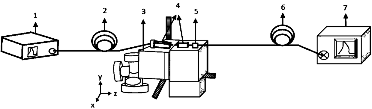
[0046] Combine below figure 1 , 2 , 3, 4 illustrate this embodiment, the present invention is an optical fiber micro-displacement sensing and correction device and method, which can detect the change of the position of the optical fiber with high sensitivity, long distance, and real-time, so as to perform correction and enhance the controllability of the optical fiber , the operation is simple and easy to implement, and it solves the problem that the small deviation of the optical fiber caused by the small size of the optical fiber is difficult to find and correct when the position of the outgoing light of the optical fiber is specified.

[0047] The optical fiber micro-displacement sensing and correction device is composed of a light source 1, a three-dimensional micro-displacement platform 3, an optical fiber fixture 4, a micro-displacement SPR sensing probe 5, a gradient multimode optical fiber 6 and a spectrometer 7;

[0048] The light source 1 is a supercontinuum light s...


PUM


Abstract

The invention provides an optical fiber micro-displacement sensing and calibrating device and method. The position change of the optical fiber can be remotely monitored in real time in a high sensitivity way. The device can also calibrate the position. The light emergent end of a light source is connected with the light input end of a measured single-mode optical fiber. The measured single-mode optical fiber and a gradient multimode optical fiber equipped with a micro-displacement SPR sensing probe are fixed on a three-dimensional micro-displacement platform through optical fiber clips with the two end surfaces opposite. . The light emergent end of the gradient multimode optical fiber is connected with the receiving end of a spectrograph. The SPR phenomenon occurs when the light is transmitted to the gradient multimode optical fiber to the SPR sensing probe through the measured single-mode optical fiber. If the position of the measured single-mode optical fiber has micro-displacement,the transmission path of the light in the gradient multimode optical fiber changes, and the SPR incident angle and resonance trough position changes so as to realize micro-displacement sensing. The reference sensing spectrum of the measured single-mode optical fiber is marked, and the sensing reference spectrum of different micro-displacement is summarized. The sensing reference spectrum is compared and the three-dimensional micro-displacement platform is adjusted so that the sensing spectrum and the reference spectrum are enabled to be overlapped in case of micro-displacement calibration.

Description

technical field [0001] The invention relates to a displacement sensing technology, more specifically to an optical fiber micro-displacement sensing and correction device and method. Background technique [0002] As an important information transmission medium in modern society, optical fiber plays a pivotal role in people's lives. Due to its advantages of good electrical insulation, high temperature and high pressure, oxidation resistance, and ability to work in flammable, explosive, chemically stable, toxic and other environmental conditions, it has become an indispensable part of communication, monitoring and medicine. [0003] Optical fiber Surface Plasmon Resonance (SPR) sensors are mainly used to sense and transmit changes in a certain physical quantity in the external environment. The physical quantity can be temperature, liquid refractive index, pressure, etc. This technology is widely used in biology, medicine, sensing, etc. field has been widely used. In 1902 at t...

Claims


Application Information

Patent Timeline
Patent Type & Authority Applications(China)
IPC IPC(8): G01B11/02
CPCG01B11/02
Inventor 马翔
Owner 安徽三汇电子科技有限公司
Why Eureka
Try Eureka