

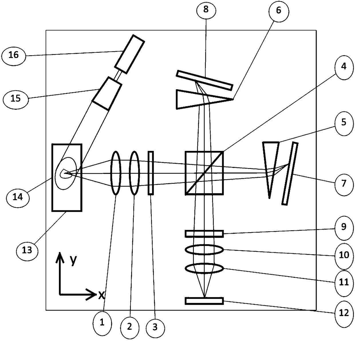
Optical path structure of spatial heterodyne Raman imaging spectrometer
An imaging spectrometer and space technology, used in Raman scattering, instruments, scientific instruments, etc., can solve the problems of low measurement efficiency and achieve the effect of rapid acquisition
- Summary
- Abstract
- Description
- Claims
- Application Information
AI Technical Summary
Problems solved by technology
Method used
Image

Examples
Embodiment Construction
[0019] In order to enable those skilled in the art to better understand the solutions of the present invention, the following will clearly and completely describe the technical solutions in the embodiments of the present invention in conjunction with the drawings in the embodiments of the present invention. Obviously, the described embodiments are only It is an embodiment of a part of the present invention, but not all embodiments. Based on the embodiments of the present invention, all other embodiments obtained by persons of ordinary skill in the art without making creative efforts shall fall within the protection scope of the present invention.
[0020] Please see figure 1 , is the optical path structure of the spatial heterodyne Raman imaging spectrometer of the present invention, which can measure both the reflection Raman spectrum and the transmission Raman spectrum of the item.
[0021] Please see figure 1 , is the X-axis and Y-axis of the space Cartesian coordinate sy...
PUM
 Abstract
Description
Claims
Application Information