Measurement method for battery welding quality

A technology of welding quality and measurement method, applied in the direction of material resistance, etc., can solve the problem of battery secondary damage accuracy, etc., and achieve the effect of rapid measurement

Inactive Publication Date: 2018-06-19
HARBIN UNIV OF SCI & TECH
6 Cites 15 Cited by

AI-Extracted Technical Summary

Problems solved by technology

[0005] The present invention is to solve the problem that the existing battery welding quality test method will ca...

Abstract

Relating to the battery measurement field, the invention provides a measurement method for battery welding quality, and aims to solve the problem that the existing battery welding quality test methodcan cause secondary damage or poor accuracy to batteries. The measurement method for battery welding quality provided by the invention includes: inputting current Ibc between a battery electrode and an electrode slice welded on the electrode, detecting the voltage Uad between the battery electrode and the electrode slice to acquire the resistance value Rx of a solder joint between the battery electrode and the electrode slice, judging whether the resistance value of the solder joint is smaller than a standard threshold, if the Rx is smaller than the standard threshold, indicating excellent welding quality, otherwise indicating poor welding quality. The measurement method provided by the invention is suitable for detection of battery welding quality.

Application Domain

Technology Topic

VoltageBattery electrode +2

Image

  • Measurement method for battery welding quality
  • Measurement method for battery welding quality
  • Measurement method for battery welding quality

Examples

  • Experimental program(1)
  • Effect test(1)

Example Embodiment

Specific embodiment
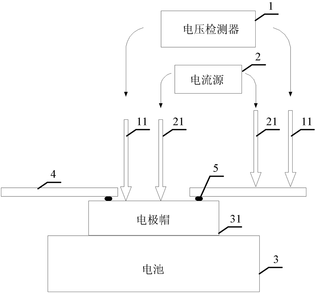
[0026] In this embodiment, the battery adopts an 18650 lithium iron phosphate 1.5Ah/3.2V single battery, and its electrode cap is circular, with a diameter of 12 mm, and a flat surface. The voltage detector is a voltage detection device that receives the signal from the controller and collects the voltage V ad. Specifically, in this embodiment, the high-speed analog-to-digital converter AD9220 of Analog Devices is used to realize signal collection. The highest sampling rate of AD9220 can reach 10 MHz, and an external crystal oscillator of 8 MHz is used, and signal storage is realized by sampling inside the FPGA. The voltage signal of the battery module can be collected and converted into a digital signal for output. The current source adopts ZM20-12ET switching controlled DC constant current power supply, the controlled output current range is 1-10A, the maximum output voltage is limited to 3V, and the current accuracy is 0.2%. It can accept the control signal of the controller to accurately adjust the output current. The controller uses a digital signal processor DSP. Digital signal processor DSP is composed of a large-scale or very large-scale integrated circuit chip, and is used to complete signal processing tasks. In order to realize the fast calculation function, the digital signal processor uses the TMS320F2812DSP application system board. The TMS320F2812DSP application system board has a digital-to-analog converter and an analog-to-digital converter, so it is a preferred signal processing and control device. The display receives the voltage of the voltage detector and the controller and displays it. Specifically, it adopts TPC-150T-ATOM model 15-inch industrial-grade tablet computer, 15-inch true color LCD display, resolution 1024x768, equipped with common industrial control interfaces, and the hard disk adopts a unique anti-vibration design, which can store one year's transmission data for quality management And for statistical analysis. It adopts 6~30V DC power input to meet the anti-interference power supply of industrial scene.

PUM

PropertyMeasurementUnit
Resistance9.0
Resistance3.5
Resistance5.6
tensileMPa
Particle sizePa
strength10

Description & Claims & Application Information

We can also present the details of the Description, Claims and Application information to help users get a comprehensive understanding of the technical details of the patent, such as background art, summary of invention, brief description of drawings, description of embodiments, and other original content. On the other hand, users can also determine the specific scope of protection of the technology through the list of claims; as well as understand the changes in the life cycle of the technology with the presentation of the patent timeline. Login to view more.

Similar technology patents

Shoot error compensating method and device and weapon system computer

InactiveCN1432786AAccurate shooting errorQuick measurementSighting devicesWeapon control systemsEngineeringData input
Owner:OERLIKON CONTRAVES BESCHRAENKTER HAFTUNG

Classification and recommendation of technical efficacy words

Why Eureka
Try Eureka