Cooling structure for direct-current superconducting current limiter and assembling method thereof

A technology of superconducting current limiter and cooling structure, applied in superconducting magnets/coils, emergency protection circuit devices for limiting overcurrent/overvoltage, circuit devices, etc., can solve the problem that DC withstand voltage cannot meet system requirements, etc. problem, to avoid bubble discharge phenomenon, facilitate heat dissipation, and facilitate installation

Pending Publication Date: 2018-06-19
TEBIAN ELECTRIC APP CO LTD +1
View PDF0 Cites 4 Cited by
  • Summary
  • Abstract
  • Description
  • Claims
  • Application Information

AI Technical Summary

Problems solved by technology

[0005] In view of the fact that the existing high-voltage AC superconducting current limiter cannot be directly applied in the DC field, and there is a phenomenon that the DC withstand voltage cannot meet the system requirements, the present invention provides a DC superconducting current limiter that can be applied to the high-voltage DC superconducting current limiting system. Cooling structure for flow device and assembly method thereof

Method used


Image

  • Cooling structure for direct-current superconducting current limiter and assembling method thereof
  • Cooling structure for direct-current superconducting current limiter and assembling method thereof

Examples


Embodiment Construction

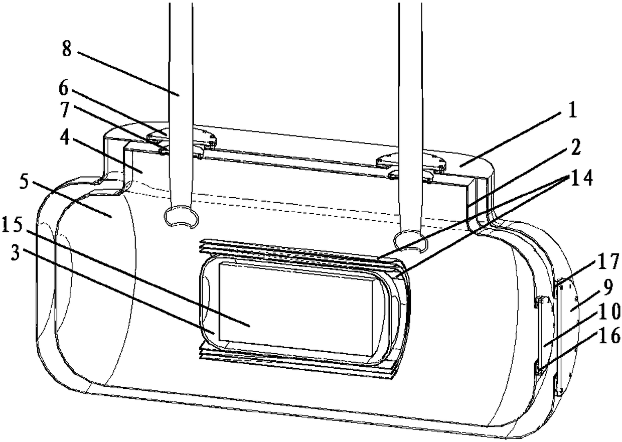
[0032] Such as figure 1 As shown, a cooling structure for a DC superconducting current limiter of the present invention includes a double-layer vacuumized structure formed by a tank body 5 and an inlet and outlet line part 4 connected to the upper part of the tank body 5, and a magnet is placed in the inner layer of the double-layer vacuumized structure 15 and the cooling liquid, the interlayer is a vacuum layer, the manhole is located at the end of one side of the tank body 5, and the connection between the tank body 5 and the inlet and outlet part 4 adopts chamfers.

[0033] In this embodiment, in order to avoid sharp discharges, the connecting parts of the tank body 5 and the inlet and outlet parts 4 adopt chamfered corners.

[0034] The inner layer 2 of the double-layer vacuum structure is also provided with a magnet 15, a shielding shell 3 and an insulating cardboard 14, wherein the shielding shell 3 is a structure that cooperates with the magnet 15, and its upper part is...


PUM


Abstract

The invention relates to a cooling structure for a direct-current superconducting current limiter and an assembling method thereof. The cooling structure comprises a double-layer vacuumizing structureformed by a tank and an inlet-outlet line part connected to the upper portion of the tank, a magnetic body and cooling liquid are put into an inner layer of the double-layer vacuumizing structure, aninterlayer is a vacuum layer, a manhole is formed in the end of one side of the tank, and a lead angle is used in the connecting part between the tank and the inlet-outlet line part; a shielding shell and paperboards are also arranged on the inner layer of the double-layer vacuumizing structure, wherein the shielding shell is of a structure matched with an inner lay of the tank, a plurality of exhausting holes are formed in the upper portion of the shielding shell, and a plurality of liquid feeding holes are formed in the lower portion of the shielding shell; the paperboards are arranged on the outer side of the shielding shell and are of structures matched with the shielding shell, and the multiple layers of paperboards are sleeved. According to the cooling structure for the direct-current superconducting current limiter and the assembling method thereof, the bubble rising speed is increased, the liquid flow speed is increased, a superconducting magnet can be radiated, and the superconducting state is rapidly recovered; the outlet line part is of an extending rectangular structure, the distance between the shielding shell and the ground in a bubble forming area is increased during rapid cooling, it is avoided that the bubbles are discharged, and the problem of high-voltage alternating-current and direct-current insulation tolerance during rapid cooling is solved.

Description

technical field [0001] The invention relates to a DC superconducting current limiter, in particular to a cooling structure for a DC superconducting current limiter and an assembly method thereof. Background technique [0002] Flexible DC transmission is an important means for large-scale access and large-scale interconnection of non-renewable resources in the future. However, the existing large-scale flexible direct transmission projects do not have the ability to clear DC line faults. The superconducting DC current limiter developed based on the unique characteristics of superconductors can suppress the short-circuit current of the line, reduce the technical requirements such as the breaking time and breaking capacity of the high-voltage DC circuit breaker, thereby improving the reliability and safety of the large-capacity flexible direct transmission system , has significant technical advantages and application value. [0003] Internationally, the development of supercon...

Claims


Application Information

Patent Timeline
Patent Type & Authority Applications(China)
IPC IPC(8): H01F6/04H02H9/02
CPCH01F6/04H02H9/023
Inventor 崔箫党艳阳贾贺强赵旭阳钟连宏段新辉宋萌李力
Owner TEBIAN ELECTRIC APP CO LTD
Why Eureka
Try Eureka