Charging bow type electric car charging system
An electric vehicle and charging system technology, applied in electric vehicle charging technology, electric vehicles, charging stations, etc., can solve the problems of inability to realize automatic positioning and intelligent charging of electric vehicles, high labor intensity of charging, and high cost of electric vehicles, and achieve cost Low, labor-intensive, high-intelligence effects
- Summary
- Abstract
- Description
- Claims
- Application Information
AI Technical Summary
Problems solved by technology
Method used
Image

Examples
Embodiment Construction
[0029] In order to further explain the technical means and effects of the present invention to achieve the intended purpose of the invention, the specific implementation and structure of a charging bow-type electric vehicle charging system proposed according to the present invention will be described below in conjunction with the accompanying drawings and preferred embodiments. , features and their effects are described in detail below.
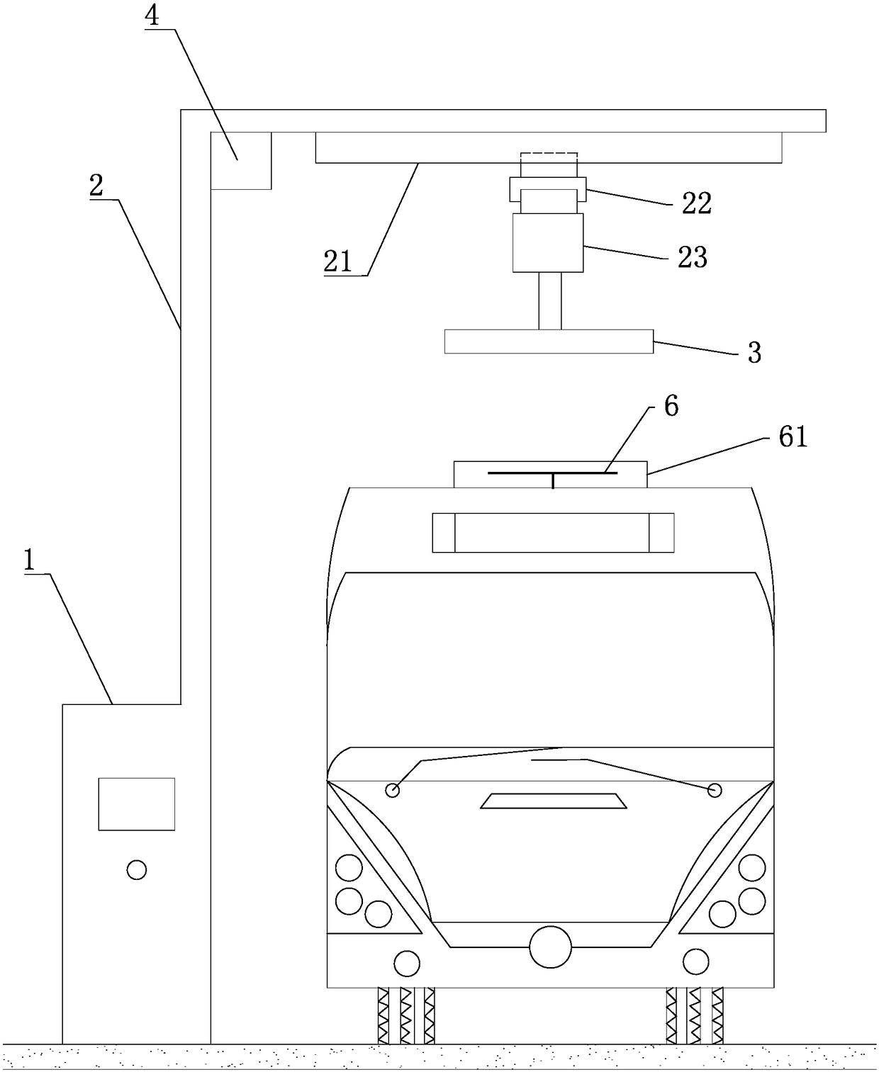
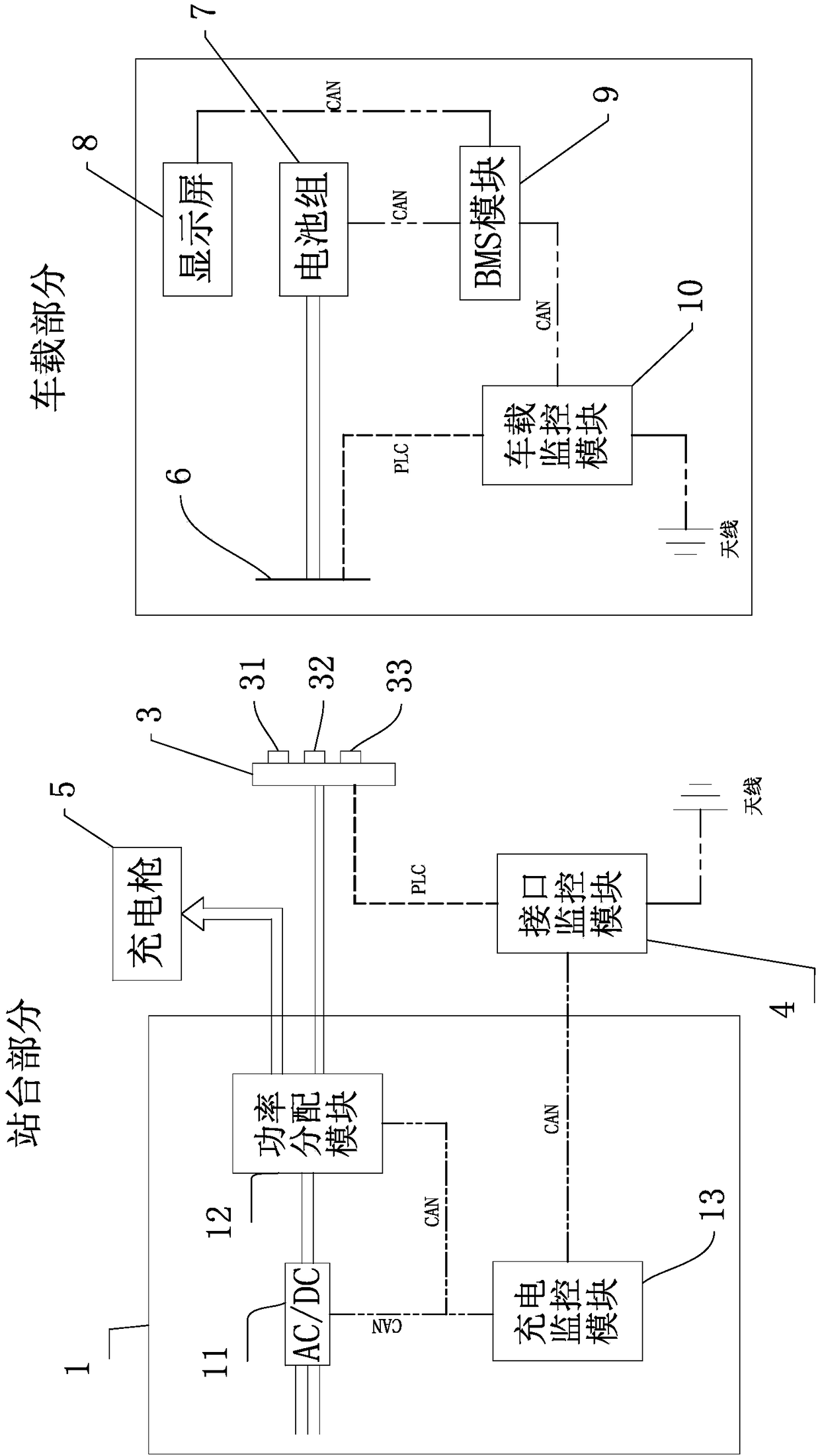
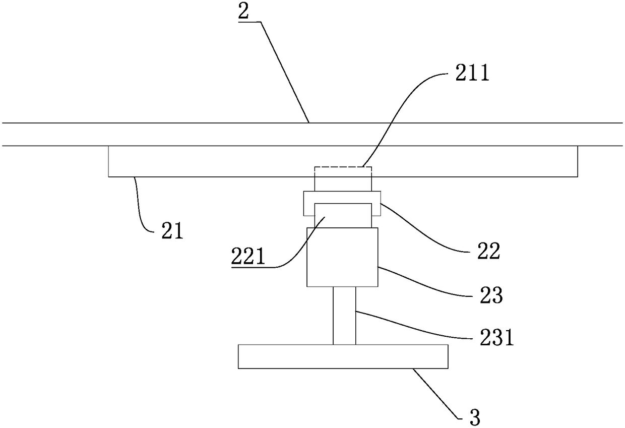
[0030] see Figure 1 to Figure 4 , a charging bow type electric vehicle charging system of the present invention includes a platform part and a vehicle part, and the platform part is installed on the platform. The platform part includes a rectifier cabinet 1, a charging rack 2, a charging bow 3, and an interface monitoring module 4. The rectifying cabinet 1 is connected to the charging rack 2, and the charging rack 2 is connected to the charging bow 3 through the charging bow traveling mechanism. The interface monitors The module 4 is arrang...
PUM
 Abstract
Description
Claims
Application Information