Assembly type full connecting liquid floating disc

A prefabricated, liquid floating technology, applied in packaging, transportation and packaging, containers, etc., can solve the problems of oil and gas volatilization, enlargement, and the self-heaviness of steel floating plates

Active Publication Date: 2018-06-22
JIANGSU DEDA AUTOMATION EQUIP
View PDF22 Cites 5 Cited by
  • Summary
  • Abstract
  • Description
  • Claims
  • Application Information

AI Technical Summary

Problems solved by technology

[0002] Most of the domestic vertical cylindrical storage tanks use buoy-type floating discs, and the edge seals adopt tongue-shaped seals, capsule-type seal structures, and even use secondary seals. It is difficult to avoid volatilization of oil and gas in the oil and gas space. The scope of application of the tongue seal and bladder seal structure is limited. When the gap between the floating plate and the tank wall is large, oil and gas leakage will occur, and this type of structure insulates the floating plate and the tank wall. There is a lot of static electricity, which poses a safety hazard
Domestically, steel floating plates are also used on cylindrical storage tanks, commonly known as iron floating tanks, which can fully contact the liquid surface, and there is no volatilization in the tank, which is firm and safe. However, steel floating plates are heavy, easy to damage, and are not resistant to corrosion. High, there are hidden dangers such as weld corrosion, oil and gas leakage, chuck, sinki...

Method used


Image

  • Assembly type full connecting liquid floating disc
  • Assembly type full connecting liquid floating disc
  • Assembly type full connecting liquid floating disc

Examples


Embodiment Construction

[0036] The present invention will be further described below.

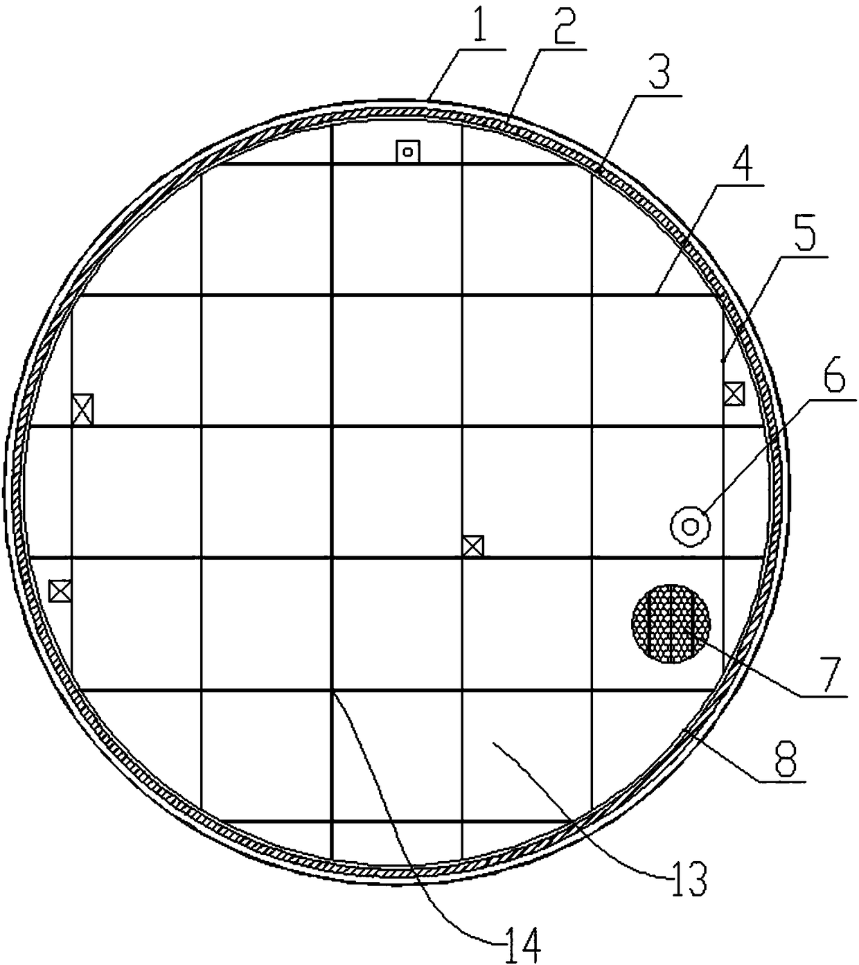
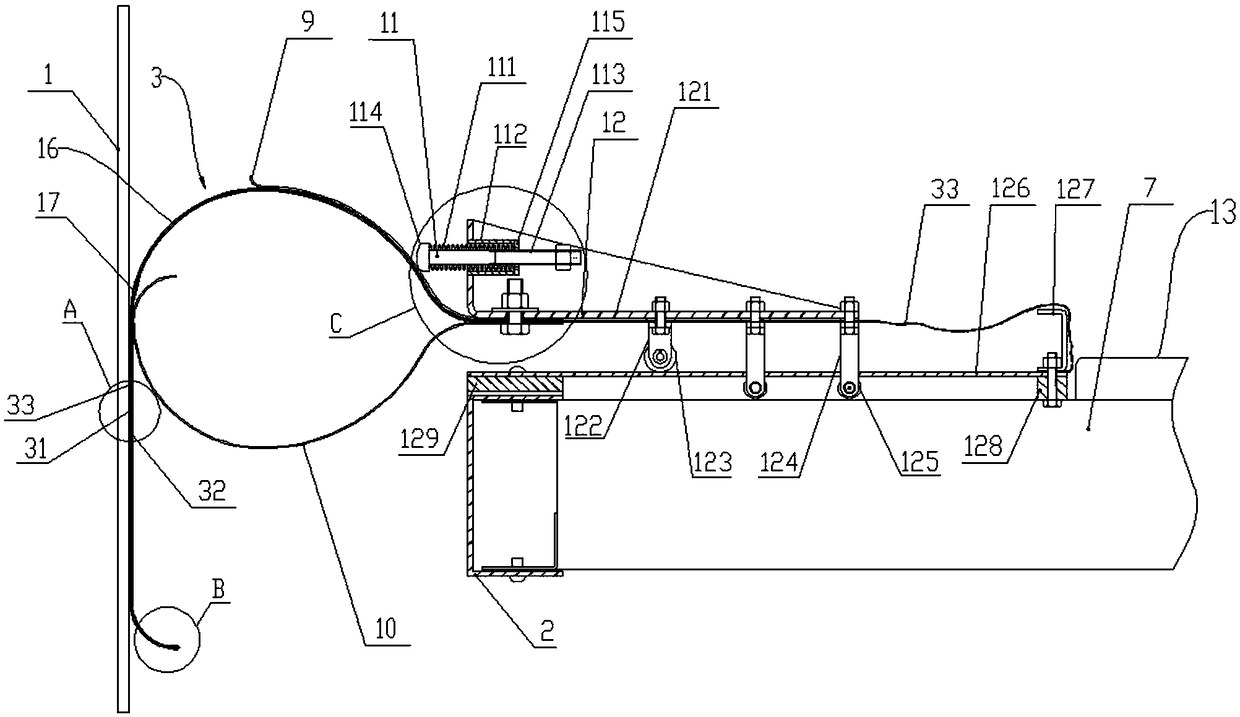
[0037] Such as Figure 1 to Figure 7 As shown, an assembled full liquid contact floating plate includes a floating device 12, a static conduction device 8 and an automatic compensation mechanism 11; 1. An annular spacer 128 located on the inner side of the inner ring of the bracket 121 and fixed on the upper surface of the floating disc body 13 concentrically with the floating disc body 13; The track unit 15 and the floating disc body 13 include an annular outer ring beam 2 located on the outside and a lattice formed by intersecting several main beam sealing connection modules 4 and auxiliary beam sealing connection modules 5 arranged vertically inside the outer ring beam. The disc-shaped framework 14 of the grid structure is provided with a sealing device 3 cooperating with the tank wall 1 on the outer side of the outer ring beam 2, and several buoyancy units are formed in several lattices of the grid structure ...


PUM


Abstract

An assembly type full connecting liquid floating disc is disclosed. A floating device comprises a floating disc body, an annular support, first annular cushion blocks and a rail unit. The rail unit comprises a pair of rail pressing plates. The two ends of the rail pressing plates are fixed to the floating disc body through the cushion blocks. The support is supported on the upper portion of the floating disc body through a sliding support mechanism acting on the rail pressing plates. A seal device comprises a first seal film, a plurality of outer elastic plates and inner elastic plates which are arranged annularly. The first seal film is laid between the outer side face of the floating disc body and the tank wall. The inner end of the first seal film is fixed to the floating disc body. Theouter end of the first seal film is clamped by the outer elastic plates to form an elastic seal mechanism in sliding seal fit with the tank wall. An automatic compensation mechanism comprises a plurality of compensation units. Guide columns in the compensation units act on the outer sides of the upper portions of highly elastic pressing plates elastically through compression springs. The assemblytype full connecting liquid floating disc can conduct elastic automatic compensation along with floating of the floating disc and is in close contact with the tank wall all the time, the seal effectcan be improved significantly, and a static electrical conductivity device is free of potential safety hazards.

Description

technical field [0001] The invention relates to the technical field of oil storage equipment, in particular to an assembled fully liquid-contacted floating plate. Background technique [0002] Most of the domestic vertical cylindrical storage tanks use buoy-type floating discs, and the edge seals adopt tongue-shaped seals, capsule-type seal structures, and even use secondary seals. It is difficult to avoid volatilization of oil and gas in the oil and gas space. The application range of the tongue seal and bladder seal structure is limited. When the gap between the floating plate and the tank wall is large, oil and gas leakage will occur, and this type of structure insulates the floating plate and the tank wall. There is a large amount of static electricity, which poses a safety hazard. In China, steel floating plates are also used on cylindrical storage tanks, commonly known as iron floating tanks, which can fully contact the liquid surface, and there is no volatilization i...

Claims


Application Information

Patent Timeline
IPC IPC(8): B65D88/42
CPCB65D88/42Y02A20/204
Inventor 张晋李继平
Owner JIANGSU DEDA AUTOMATION EQUIP
Why Eureka
Try Eureka