Particulate loading amount calculating method for particulate filter and device thereof

A particle trap, particle technology, used in computing, mufflers, exhaust devices, etc., to solve problems such as changes, heavy work, and inaccurate results

Active Publication Date: 2018-06-22
湖南矢田科技有限责任公司
View PDF5 Cites 5 Cited by
  • Summary
  • Abstract
  • Description
  • Claims
  • Application Information

AI Technical Summary

Problems solved by technology

[0010] In order to solve the problem that the calibration of the MAP map is heavy work, the result is inaccurate, and the real MAP map will change with the different engine operating conditions, this calculation method directly skips the calibration of the MAP map, and uses the theoretical pressure drop model to inverse Push method to calculate particle loading

Method used


Image

  • Particulate loading amount calculating method for particulate filter and device thereof
  • Particulate loading amount calculating method for particulate filter and device thereof
  • Particulate loading amount calculating method for particulate filter and device thereof

Examples


Embodiment Construction

[0023] The present invention will be further described below in conjunction with accompanying drawing.

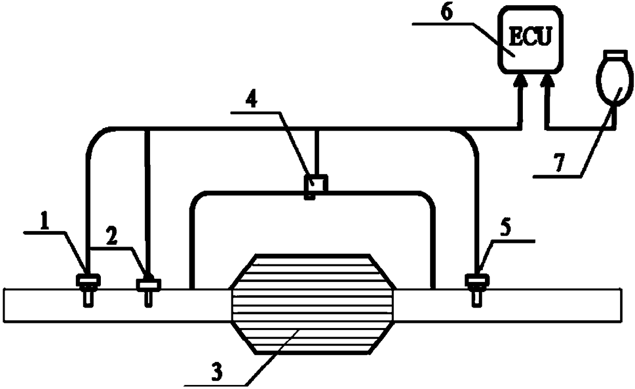
[0024] Such as figure 1 As shown, the hardware device of the calculation method includes a temperature sensor 1 for monitoring the temperature signal at the front end of the particle trap. Oxygen sensor 2 is used to correct the air mass flow rate and fuel consumption rate. Particle trap 3, as a carrier for particle deposition. The differential pressure sensor 4 transmits the differential pressure signal at both ends of the particle trap to the ECU. The temperature sensor 5 is used to correct the temperature at the front end of the particle trap. ECU6 is used to receive and process signals such as temperature, differential pressure, oxygen concentration, fuel consumption rate, and air mass flow. The air mass flow meter 7 monitors the intake air quality signal of the engine intake pipe and transmits it to the ECU.

[0025] In this calculation method, the ECU records the ...


PUM


Abstract

The invention discloses a particulate loading amount calculating method for a particulate filter. The calculating method comprises the steps of judging the Peclet number of a particulate settled layer, calculating the micro-parameter of the particulate settled layer, backwards reasoning the thickness and the loading amount of the particulate settled layer according to the pressure drop, and calculating the particulate loading saturation. A device comprises an ECU, a pressure sensor, a temperature sensor, an oxygen sensor, an air mass flow rate sensor and the like. According to the purpose of the invention, by considering that under the different working conditions of an engine, the particulate deposited microstructures are different, the loading amount of particulates in the particulate filter is calculated through a theoretic pressure drop model, and accordingly, the regeneration opportunity is precisely controlled; and meanwhile, the particulate loading saturation is calculated to represent the loading degree of the particulate filter, and the positive effects on particulate filter service life prolonging and renewable energy consumption reducing are well achieved.

Description

technical field [0001] The invention relates to a method and device for calculating the particle load of a particle trap Background technique [0002] Among the current diesel particulate aftertreatment technologies, the particulate filter is considered to have the most application prospect and development potential. There are two main difficulties in the application of particle traps. One is the selection of filter material, which must have high filtration efficiency, low flow resistance, and good high temperature resistance and mechanical strength. The second is the regeneration of the carrier, that is, after the particle filter has been working for a period of time, the particle deposition reaches a certain level, and the pressure drop at both ends of the particle filter reaches the limit value, which affects the normal particle capture and engine operation. Particles deposited in the pores of the carrier are removed. Among them, the technical difficulties of the former...

Claims


Application Information

Patent Timeline
Patent Type & Authority Applications(China)
IPC IPC(8): F01N3/023F02D41/02G06F17/50
CPCF01N3/023F02D41/029F02D41/1441F02D41/1445F02D41/1448F02D2041/1433G06F30/20
Inventor 龚金科刘伟强刘冠麟李炯
Owner 湖南矢田科技有限责任公司
Why Eureka
Try Eureka