
Double-layer nanometer optical grating-based micro-nano gyroscope and processing method thereof

A nano-grating and gyroscope technology, applied in the micro-opto-electromechanical and inertial navigation fields, can solve problems such as difficulty in balancing accuracy and dynamic performance, capacitance detection is easily interfered by parasitic effects, and limits the application of micro-electromechanical gyroscopes, etc., achieving good market prospects , small mass, free from electromagnetic interference

Active Publication Date: 2018-06-22
SOUTHEAST UNIV
View PDF8 Cites 3 Cited by
  • Summary
  • Abstract
  • Description
  • Claims
  • Application Information

AI Technical Summary

Problems solved by technology

In this solution, capacitance detection is easily disturbed by parasitic effects, and it is difficult to balance accuracy and dynamic performance, which limits the application of MEMS gyroscopes in many fields that require high measurement accuracy

Method used


Image

  • Double-layer nanometer optical grating-based micro-nano gyroscope and processing method thereof
  • Double-layer nanometer optical grating-based micro-nano gyroscope and processing method thereof
  • Double-layer nanometer optical grating-based micro-nano gyroscope and processing method thereof

Examples


Embodiment 1

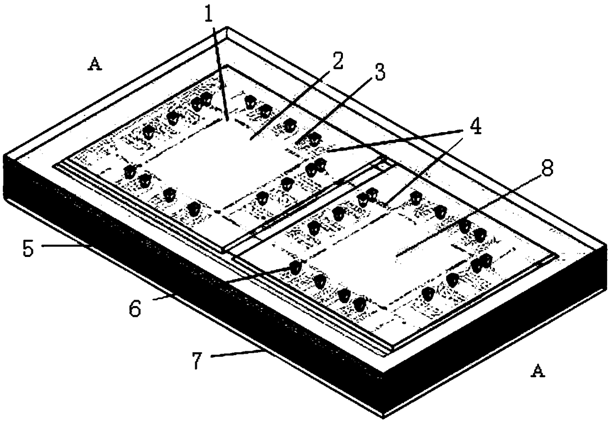
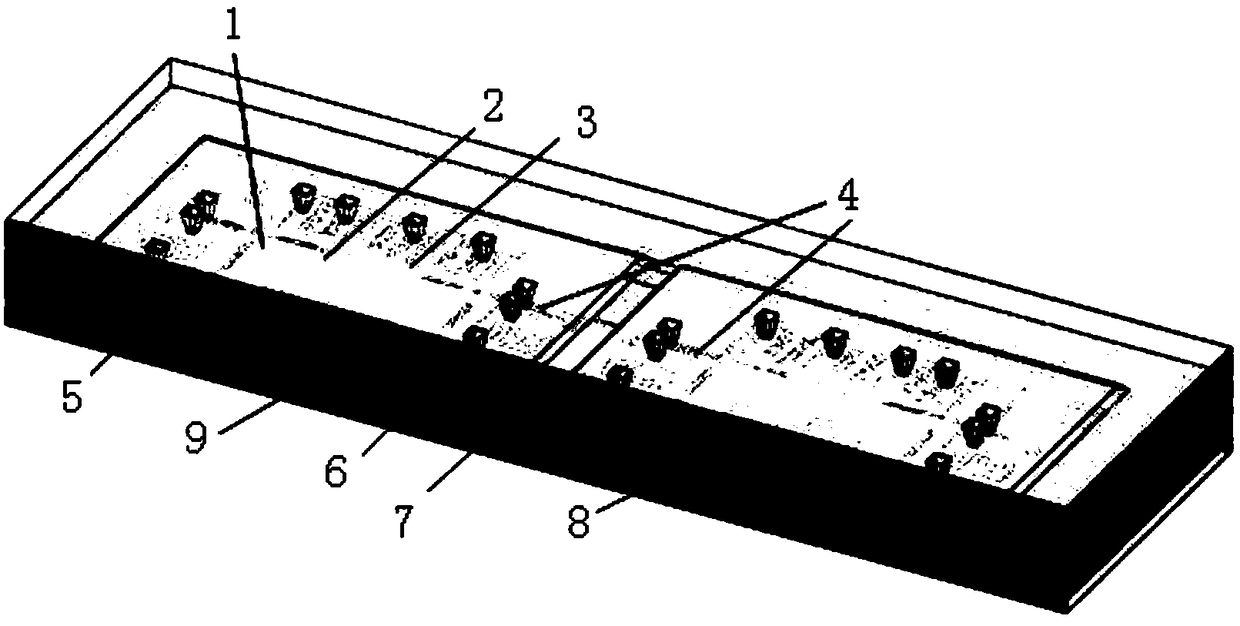
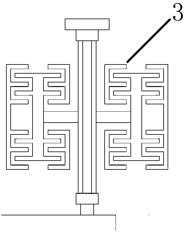
[0037] Such as Figure 1-4As shown, a micro-nano gyroscope based on a double-layer nano-grating includes a glass substrate 7, a support structure, a double-mass microresonator 1 and a glass cap 5. The support structure is a topless box structure, and the glass lining The bottom 7, the support structure and the glass cap 5 are sequentially connected from bottom to top to form a cavity structure, and the double-mass microresonator 1 is arranged in the support structure; the double-mass microresonator 1 includes two groups of symmetrically arranged microresonators, each The set of microresonators includes a mass block 2, a driving frame 3, a decoupling beam 4 and a movable grating 8, the movable grating 8 is set at the center of the mass block 2, the driving frame 3 is set around the mass block 2, and the decoupling beam 4 is set at the center of the mass block 2. At the four corners of the mass block 2, they are respectively connected to the drive frame 3 on two adjacent sides; ...

Embodiment 2

[0053] It is basically the same as Embodiment 1, the difference is: in step 2), electron beam exposure is adopted to directly obtain the pattern and position; the device pattern can be processed together with the movable grating 8 pattern, reducing processing steps and reducing alignment errors.

[0054] The technologies not mentioned in the present invention refer to the prior art.


PUM


Abstract

The invention discloses a double-layer nanometer optical grating-based micro-nano gyroscope and a processing method thereof. The double-layer nanometer optical grating-based micro-nano gyroscope comprises a glass substrate, a supporting structure, a double-mass-block micro-resonator and a glass cover cap; the glass substrate, the supporting structure and the glass cover cap are connected with oneanother sequentially from bottom to top to form a cavity structure; the double-mass-block micro-resonator is arranged in the supporting structure; the double-mass-block micro-resonator comprises two groups of mass blocks, driving frames, decoupling beams and movable optical grating; the movable optical grating is arranged on the center part of each mass block; the driving frames are arranged at the periphery of the mass block; the decoupling beams are arranged at four corners of the periphery of the mass block; fixed optical grating is arranged at the bottom of the supporting structure under each piece of movable optical grating; electrode through holes are formed in the glass cover cap and corresponding to the position of the driving frame uniformly; and a metal welding pad connected withthe driving frame is arranged in each electrode through hole. The double-layer nanometer optical grating-based micro-nano gyroscope has the advantages of small mass, high measuring precision, insusceptibility to electromagnetic interference and convenience in batched production, and has wide application range and good market prospect.

Description

technical field [0001] The invention relates to a micro-nano gyroscope based on a double-layer nano-grating and a processing method thereof, belonging to the technical fields of micro-opto-electromechanical and inertial navigation. Background technique [0002] Micro-inertial devices are key devices for measuring the acceleration and angular velocity of objects, and are one of the MEMS (micro-mechanical systems) products, mainly including micro-machined accelerometers and micro-machined gyroscopes. Compared with traditional inertial devices, it has the characteristics of small size, low power consumption, low cost, and easy mass production, making it widely used in automotive consumer electronics, navigation and positioning, weapon guidance and other fields. [0003] At present, most MEMS gyroscopes adopt the scheme of Gothic effect and capacitance detection. In this solution, capacitance detection is easily disturbed by parasitic effects, and it is difficult to balance acc...

Claims


Application Information

Patent Timeline
IPC IPC(8): G01C19/58
CPCG01C19/58
Inventor 夏敦柱黄泠潮
Owner SOUTHEAST UNIV
Learn More