Time modulation array based communication and radar integrated design method

A technology of time modulation and design method, applied in radio wave measurement systems, instruments, etc., can solve the problems of unreliability, high complexity, low efficiency, etc., and achieve the effect of improved work efficiency, low complexity, and flexible work

Inactive Publication Date: 2018-06-22
HARBIN INST OF TECH
View PDF9 Cites 11 Cited by
  • Summary
  • Abstract
  • Description
  • Claims
  • Application Information

AI Technical Summary

Problems solved by technology

[0004] The purpose of the present invention is to solve the problems of high complexity of the existing integrated waveform design method, low efficiency of the integrated method based on time division, reliabil

Method used


Image

  • Time modulation array based communication and radar integrated design method
  • Time modulation array based communication and radar integrated design method
  • Time modulation array based communication and radar integrated design method

Examples


specific Embodiment approach 1

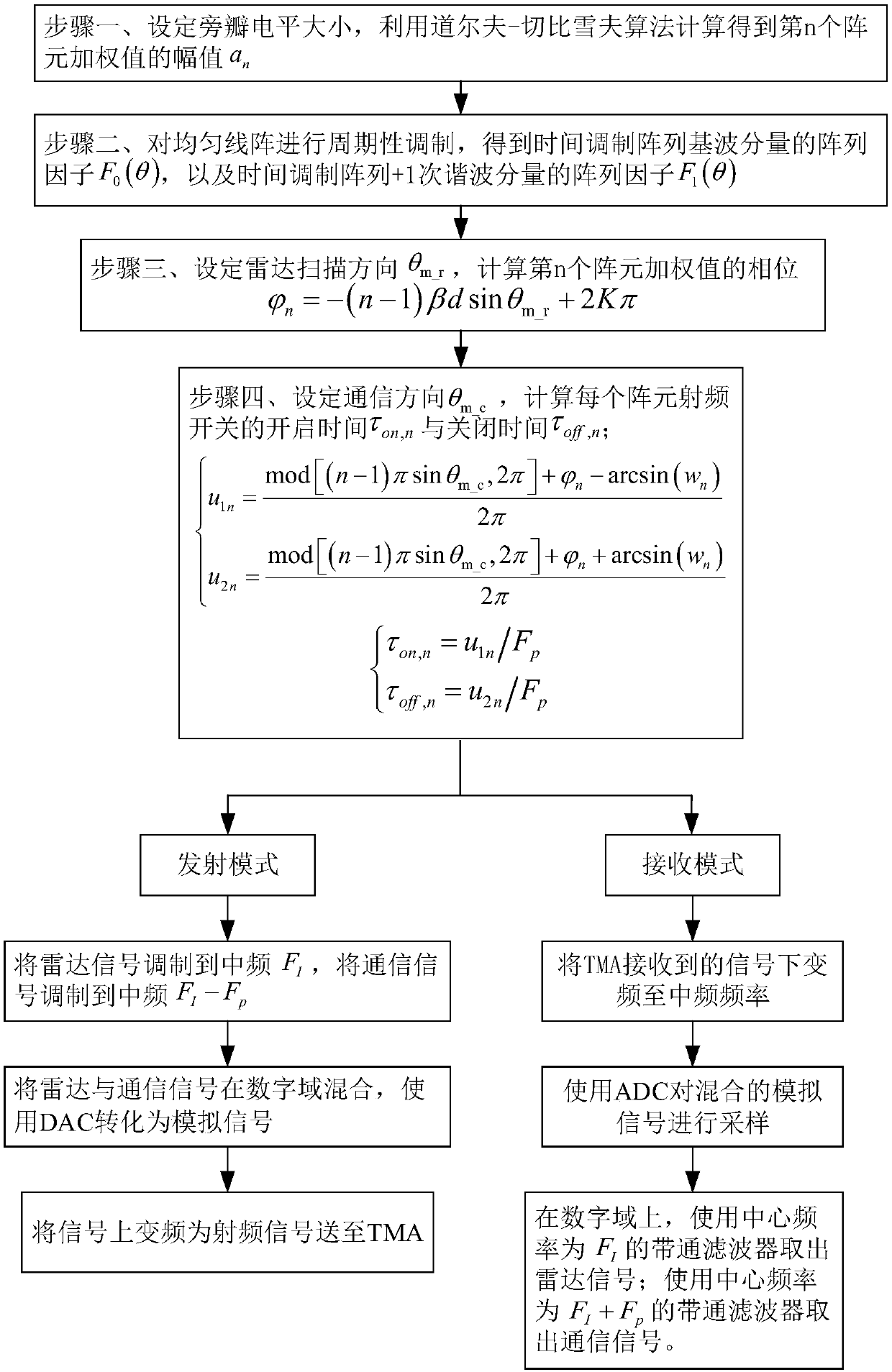
[0027] Specific embodiment one: a communication radar integrated design method based on time modulation array comprises the following steps:

[0028] Step 1: According to the expression of the array factor of the uniform linear array, use the Dolph-Chebyshev (Dolph-Chebyshev) algorithm to calculate the amplitude a of the weighted value of the nth array element n ;

[0029] Step 2: Periodically modulate the uniform linear array to obtain the array factor F of the fundamental wave component of the time-modulated array 0 (θ), and the array factor F of the time modulated array + 1st harmonic component 1 (θ);

[0030] Step 3: Set the radar scanning direction θ m_r , to calculate the phase of the weighted value of the nth array element

[0031] Step 4: Set the communication direction θ m_c , calculate the turn-on time τ of the RF switch of each array element (a total of N array elements) on,n with closing time τ off,n ;

[0032] Step 5: In the transmitting mode, the radar ...

specific Embodiment approach 2

[0034] Specific embodiment 2: The difference between this embodiment and specific embodiment 1 is: the expression of the array factor according to the uniform linear array is calculated by using the Dolph-Chebyshev (Dolph-Chebyshev) algorithm to obtain the nth array The magnitude of the meta-weighted value a n The specific process is:

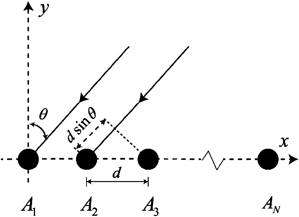
[0035] Consider an N-element uniform linear array with an element spacing of d, such as figure 1 shown;

[0036] The array factor F(θ) of the uniform linear array is expressed as:

[0037]

[0038] in, is the weighted value of the nth array element, wavenumber β=2π / λ, λ is the wavelength, θ is the incident azimuth angle of the incident wave, and ψ is the incident zenith angle of the incident wave;

[0039]Set the size of the side lobe level, and use the Dolf-Chebyshev algorithm to calculate the amplitude a of the weighted value of the nth array element n .

[0040] Other steps and parameters are the same as those in Embodiment 1.

specific Embodiment approach 3

[0041] Specific embodiment three: the difference between this embodiment and specific embodiment one or two is: the array factor F of the time-modulated array fundamental wave component is obtained 0 (θ), and the array factor F of the time modulated array + 1st harmonic component 1 The specific process of (θ) is:

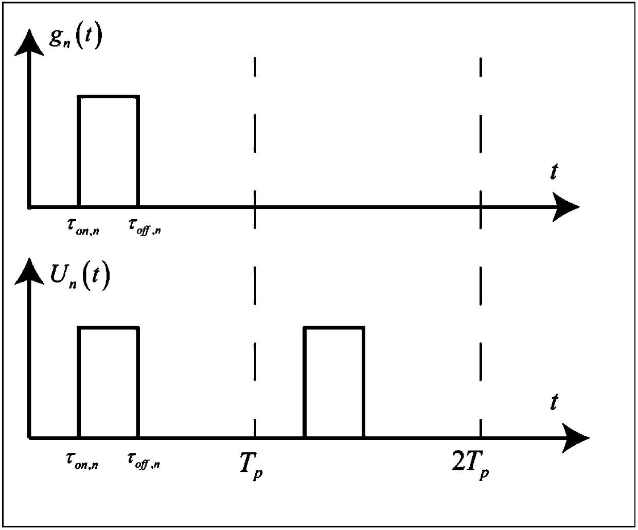
[0042] The nth array element is determined by the periodic function U n (t) modulation, expressed as:

[0043]

[0044] Where t is time, T p is the modulation period, m is the period parameter, g n (t) is the gate function, written as:

[0045]

[0046] Periodic function U n (t) AND gate function g n (t) if figure 2 shown.

[0047] Periodic function U n (t) is expanded by Fourier series as:

[0048]

[0049] where F p =1 / T p is the modulation frequency, α nk is the kth order harmonic coefficient, calculated by the following formula:

[0050]

[0051] In time-modulated arrays, equation (1) can be rewritten as:

[0052]

[0053] The arra...


PUM


Abstract

A time modulation array based communication and radar integrated design method is provided. The invention relates to a communication and radar integrated design method. The invention solves the problem that the existing integrated waveform design methods have high complexity, the time division based integrated methods are low in efficiency, the reliability of the space division based integrated methods are low, and scanning detection cannot be performed. The invention comprises: 1, calculating and obtaining an amplitude of a nth array element weighted value; 2, periodically modulating a uniform linear array, and obtaining an array factor of a fundamental component of a time modulation array and an array factor of the time modulation array +a first harmonic component; 3, calculating a phaseof the nth array element weighted value; 4, calculating the turn-on time and the turn-off time of each array element RF switch; and 5, mixing and sending a radar signal and a communication signal tothe time modulation array in the transmit mode; simultaneously receiving the radar signal and the communication signal in the receiving mode, and using a band pass filter to perform distinguishing. The invention is used in the field of communication and radar integration.

Description

technical field [0001] The invention relates to the field of integrated design of communication radars, in particular to a method for integrated design of communication radars based on time modulation arrays. Background technique [0002] The coexistence technology of radar system and communication system has always been a research hotspot. The combination of communication and radar can give full play to their respective advantages, make up for each other's shortcomings, and greatly improve the overall combat power. First, the main functions of the current AWACS radar are active detection, target positioning, and target guidance. Since AWACS often work in harsh electromagnetic environments and targeted electronic interference, its communication capabilities will be greatly reduced. Therefore, the anti-interference ability of communication is one of the key factors to determine whether the system can play an important role. Second, in order to adapt to the modern combat env...

Claims


Application Information

Patent Timeline
IPC IPC(8): G01S7/28
CPCG01S7/28
Inventor 赵洪林单成兆马永奎张佳岩高玉龙
Owner HARBIN INST OF TECH
Why Eureka
Try Eureka