Detection method and device for high-dynamic-range optical time domain reflection

A technology of optical time domain reflectance and high dynamic range, applied in reflectometers for detecting backscattered light in the time domain, reflectometers using stimulated backscattering, and testing fiber/optical waveguide equipment, etc. Given, the absolute value of the slope is small, and the overall performance of the product is affected, so as to improve the accuracy and achieve significant effects.

Active Publication Date: 2018-06-22
GUANGXUN SCI & TECH WUHAN
View PDF9 Cites 11 Cited by
  • Summary
  • Abstract
  • Description
  • Claims
  • Application Information

AI Technical Summary

Problems solved by technology

[0005] U.S. Patent US9494484 proposes a scheme for OTDR measurement in an optical path containing a Raman amplifier, but this scheme only sends a single Raman amplified optical pulse when the OTDR detection laser sends an optical pulse. The principle is mainly through Forward Raman pumping amplifies the detection light pulse, which has a very limited effect on improving the dynamic range, and this solution has the prob...

Method used


Image

  • Detection method and device for high-dynamic-range optical time domain reflection
  • Detection method and device for high-dynamic-range optical time domain reflection
  • Detection method and device for high-dynamic-range optical time domain reflection

Examples


Embodiment 1

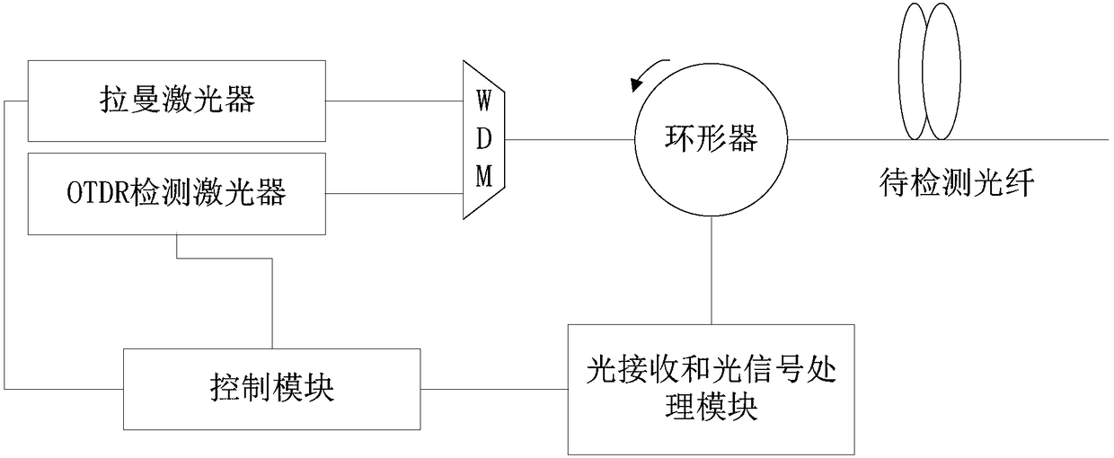
[0044] Embodiment 1 of the present invention provides a detection device for high dynamic range optical time domain reflection, such as figure 1As shown, including Raman laser, optical time domain reflectometer (Optical Time Domain Reflect-ometry, OTDR) detection laser, wavelength division multiplexer (Wavelength Division Multiplexing, abbreviated as: WDM), control module, optical receiving and optical signal processing Modules, and circulators, specifically:

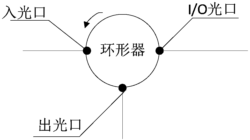
[0045] The Raman laser and the OTDR detection laser are respectively connected to the WDM, and the light outlet of the WDM is connected to the light inlet of the circulator ( figure 1 When the circulator used in the device is proposed separately to show its interface distribution, the corresponding distribution structure is as follows figure 2 shown), the pulsed light sent by the Raman laser and the OTDR detection laser is combined by the WDM and then passed through the I / O optical port of the circulator (such as fi...

Embodiment 2

[0057] After providing a detection device for high dynamic range optical time domain reflection described in embodiment 1, embodiment 2 of the present invention also proposes a detection method for high dynamic range optical time domain reflection, in the detection method It is necessary to realize the basic connection characteristics, wherein the control module is used to control the working state of the Raman laser and the OTDR detection laser, and is also used to obtain the optical signal reflected back from the optical fiber to be detected (compared with the above connection characteristics. The corresponding detection method of the invention can also be realized by the detection device set forth in embodiment 1), such as Figure 5 As shown, detection methods include:

[0058] In step 201, the Raman laser and the OTDR detection laser send Raman pulsed laser light and the OTDR detection optical signal to the optical fiber to be detected according to preset configuration par...

Embodiment 3

[0066] The embodiment of the present invention combines the detection method described in embodiment 2 and the detection device described in embodiment 1, and provides how to implement the method described in embodiment 2 in the detection device described in embodiment 1, as follows Figure 6 As shown, the method includes:

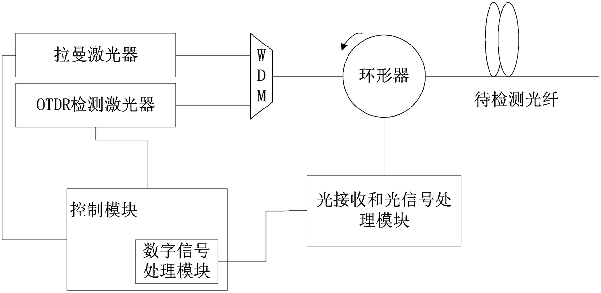
[0067] Step 301, combine the output ports of the Raman laser and the OTDR laser through WDM, and inject them into the optical fiber to be tested through a circulator. The circulator is connected with the optical receiving and optical signal processing module to convert the returned optical signal into a digital electrical signal, and then the output signal is connected to the digital signal processor processing module and the display screen.

[0068] Among them, the optical receiving and optical signal processing modules should include filters, avalanche photodiodes (APDs), amplifiers, and analog-to-digital converters. The filter can filter out the noise ...


PUM


Abstract

The invention relates to the technical field of optical time domain reflectometer, and provides a detection method and device for high-dynamic-range optical time domain reflection. The device comprises a Raman laser and an OTDR detection laser, which are respectively connected to a WDM, wherein a light outlet of the WDM is connected to a light inlet of a circulator; a light receiving and light signal processing module is connected to a light outlet of the circulator; the light receiving and light signal processing module is further connected to a control module; the control module is used forcontrolling a driving pin of the Raman laser, and controlling the Raman laser to emit at least two light pulses with a time interval in a detection time period according to the relevant information ofreflection light. According to a multi-pulse solution, the light pulses can be amplified and detected through forward Raman light pulses, the Raman light pulses can be continuously sent through the Raman laser after the OTDR detection laser is closed in order to directly amplify and detect back Rayleigh scattering light signals or Fresnel reflection light signals generated by the light pulses.

Description

【Technical field】 [0001] The invention relates to the technical field of optical time domain reflectometers, in particular to a detection method and device for high dynamic range optical time domain reflectance. 【Background technique】 [0002] At present, the communication networks of various countries in the world are mainly based on optical fiber transmission, and optical time domain reflectometer (OTDR) is usually used to test the characteristics of optical fiber when constructing and maintaining optical cable lines. OTDR is also an important device in the online monitoring system of optical communication network, and the dynamic range is one of the important technical indicators of OTDR. The larger the dynamic range of the OTDR, the longer the distance of the optical communication line that can be monitored. [0003] The working principle of OTDR is to analyze the length, attenuation, event and other characteristics of the optical fiber by detecting the energy distribut...

Claims


Application Information

Patent Timeline
IPC IPC(8): H04B10/071
CPCH04B10/071G01M11/3127G01M11/319
Inventor 周琪卜勤练熊涛付成鹏张建涛余春平乐孟辉
Owner GUANGXUN SCI & TECH WUHAN
Why Eureka
Try Eureka