Fourier cascading imaging system based on multi-angle illumination and Fourier domain coded modulation
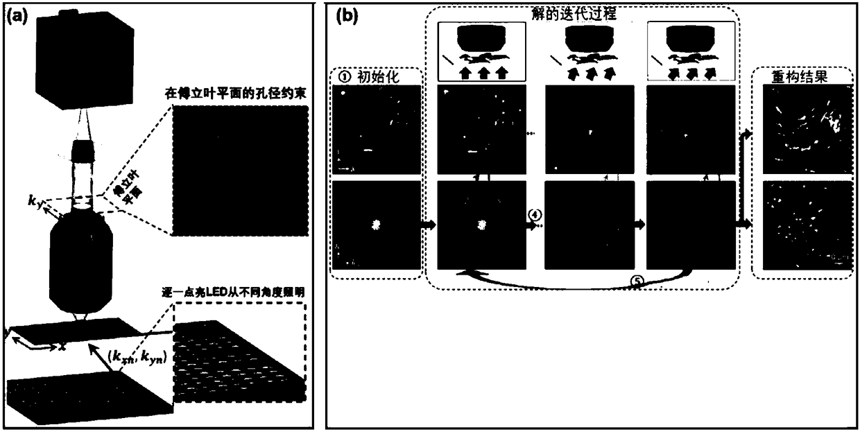
An imaging system, coding and modulation technology, applied in image acquisition, image data processing, image data processing and other directions, can solve the problems of heat dissipation and battery capacity, which restrict the miniaturization and portable design of the system, and the image reconstruction processor has a large computing load and heavy load. It can solve the problems of slow convergence speed of the construction algorithm, and achieve the effect of longer image exposure time, shorter image exposure time and easy convergence.
- Summary
- Abstract
- Description
- Claims
- Application Information
AI Technical Summary
Problems solved by technology
Method used
Image
Examples
Embodiment 1
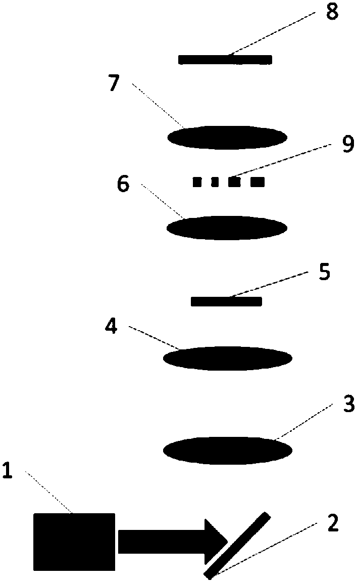
[0031] image 3 It is a Fourier stack imaging system architecture of this embodiment. The key to the implementation is to add an intensity-modulated or phase-modulated baffle to the back focal plane of the objective lens 6 in the existing imaging system, and to use a vibration-based The multi-angle illumination source of the mirror 2 replaces the conventional LED array 10 .
[0032] Such as image 3 As shown, the light beam generated by LED or laser 1 is sent to scanning lens 3 by scanning galvanometer or micro-motor galvanometer 2 . The light beam converges to the rear focal plane of the condenser lens 4 through the scanning lens 3 . After passing through the condenser lens 4, it will become parallel light and shine on the object 5. By changing the angle of the galvanometer 2, the incident angle of the parallel light will be modulated, thereby producing illumination light with different incident angles. During the imaging process, the computer sends instructions to the vi...
Embodiment 2
[0035] Figure 4 It is another Fourier stack imaging system architecture of the present invention. Similar to Embodiment 1, an intensity modulation or phase modulation baffle is added to the back focal plane of the objective lens 6 in the existing imaging system; the difference is that the imaging system of this embodiment uses traditional LED The array 10 serves as a multi-angle illumination source. As mentioned above, after adding the modulation baffle of the Fourier surface, the image reconstruction process requires fewer illumination angles, so the imaging system of this embodiment has lower performance requirements for multi-angle illumination sources than the existing Fourier stack imaging system, this embodiment can use the LED array 10 with lower cost and smaller volume.
[0036] Such as Figure 4 As shown, one LED in the LED array 10 is turned on each time to illuminate the object to be imaged at a certain incident angle. For each illumination angle, the system ac...
Embodiment 3
[0038] Figure 5 It is a simplified version of the Fourier stack imaging system of the present invention, and its compact structure is suitable for customers who need to use portable imaging equipment. One LED in the LED array 10 is turned on each time to illuminate the object 5 to be imaged at a certain incident angle. For each illumination angle, the system acquires a low-resolution image of the object to be imaged, and then all the low-resolution images are synthesized into a high-resolution image in the Fourier domain. After the light beam irradiates the object 5 to be imaged, intensity modulation or phase modulation is carried out by the coding and modulation device 9 on the Fourier surface, and photoelectric conversion is completed at the CCD or CMOS image sensor 8, and the generated digital image signal is collected and buffered by the CCD or CMOS image sensor 8. It can be output to a signal processor for Fourier domain synthesis of images to obtain high-resolution ima...
PUM
 Abstract
Description
Claims
Application Information
 - R&D
- Intellectual Property
- Life Sciences
- Materials
- Tech Scout
- Unparalleled Data Quality
- Higher Quality Content
- 60% Fewer Hallucinations
Browse by: Latest US Patents, China's latest patents, Technical Efficacy Thesaurus, Application Domain, Technology Topic, Popular Technical Reports.
© 2025 PatSnap. All rights reserved.Legal|Privacy policy|Modern Slavery Act Transparency Statement|Sitemap|About US| Contact US: help@patsnap.com


