Battery cell, electronic equipment and battery cell package method

A technology of batteries and batteries, which is applied in the field of batteries, can solve problems such as the size cannot be made large enough, the failure of batteries, the deformation of winding cores, etc., and achieve the effects of not easy to deform and fail, safe and reliable in use, and good in structural strength

Active Publication Date: 2018-06-26
XIAN ZHONGXING NEW SOFTWARE
View PDF3 Cites 15 Cited by
  • Summary
  • Abstract
  • Description
  • Claims
  • Application Information

AI Technical Summary

Problems solved by technology

The disadvantage is: because the shell is formed by stamping from aluminum, affected by the amount of deformation and material of the aluminum, the size cannot be made large enough, especially in the length direction, which causes the size of the battery cell to be limited, and the capacity of the battery cell cannot be made enough Big
The soft-pack battery is mainly a rectangular structure. The advantage is that the capacity of the battery can be made large enough and the size can be relatively large; the disadvantage is that the aluminum-plastic film on the outside of the battery is easy to deform when the whole machine is dropped, which in turn causes The winding core inside is deformed and causes the failure of the battery core, which may cause a safety accident; another disadvantage is that this kind of battery is usually pasted in the battery compartment with strong double-sided tape. If the battery n

Method used


Image

  • Battery cell, electronic equipment and battery cell package method
  • Battery cell, electronic equipment and battery cell package method
  • Battery cell, electronic equipment and battery cell package method

Examples


Embodiment 1

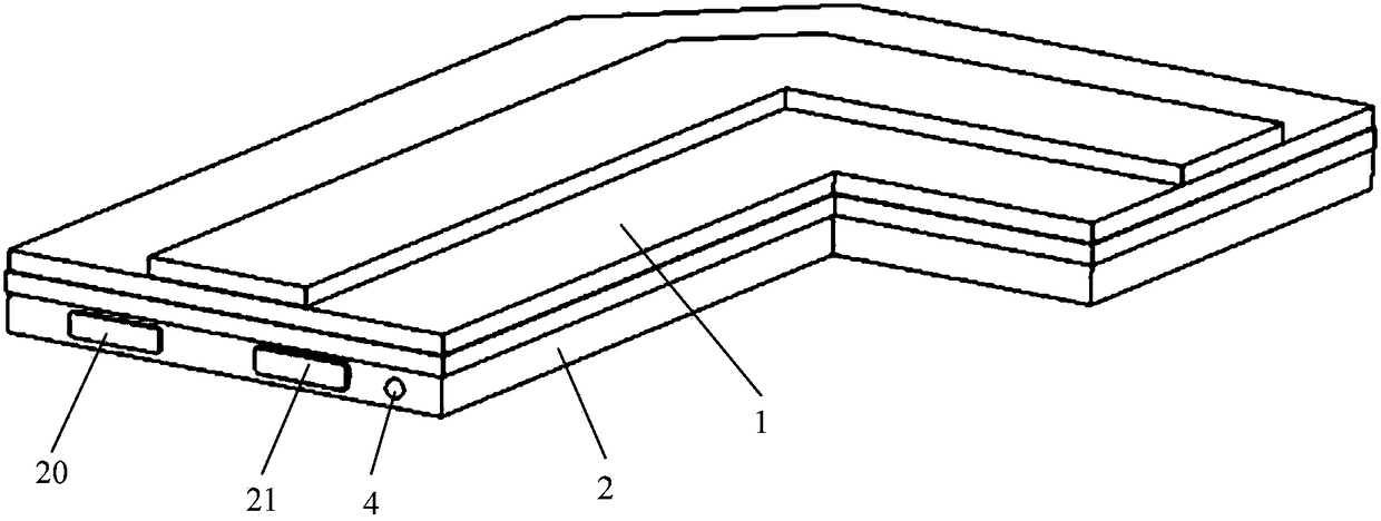
[0047] Such as figure 1 As shown, this embodiment provides a battery cell, including: a casing and a battery cell.

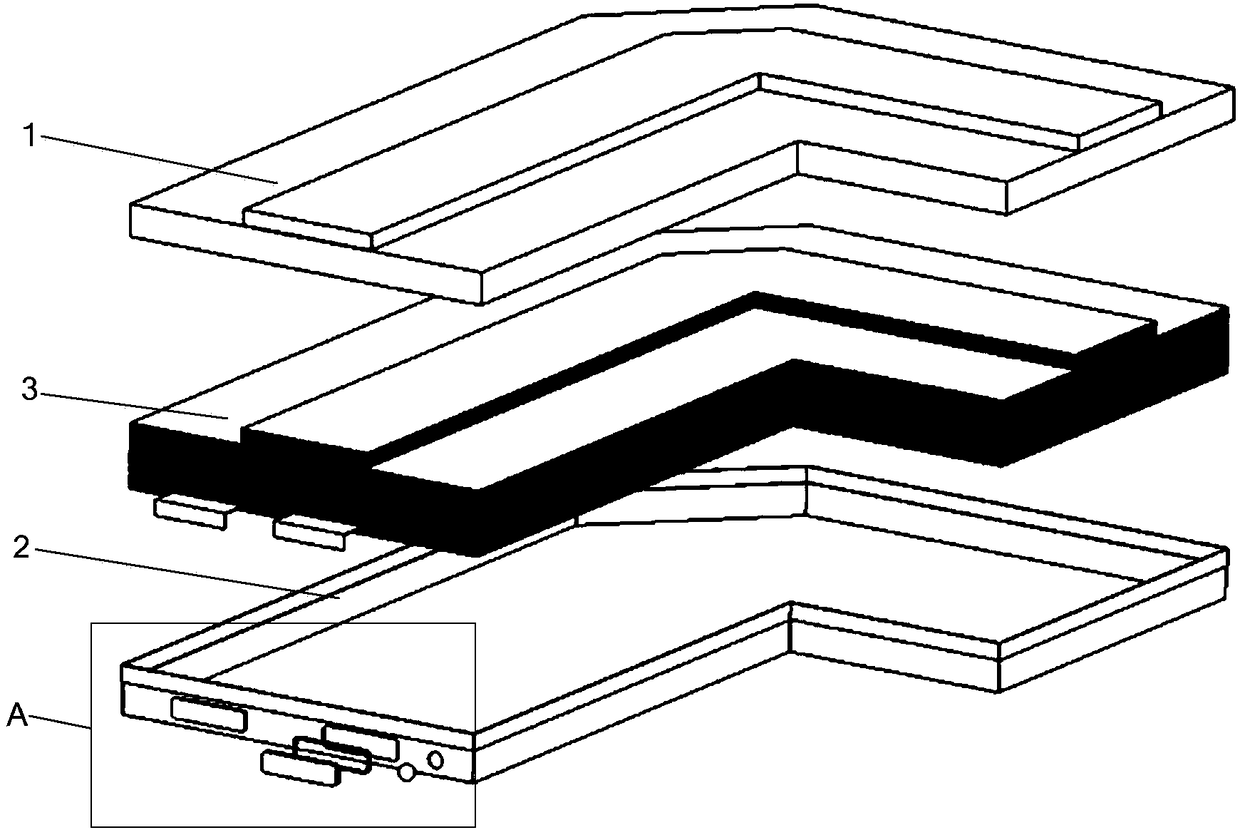
[0048] Among them, such as figure 2 As shown, the housing includes a steel lower shell 2 and a steel upper shell 1. Due to the good rigidity of the steel material, it is easy to form, so that the upper shell 1 and the lower shell 2 can be made into various sizes and shapes ( Such as special-shaped shape), so that the shell can be in various shapes, so as to be able to adapt to the design requirements of electronic devices such as mobile phones or wearable devices.

[0049] In addition, due to the weldability of the steel material, the lower shell 2 and the upper shell 1 can be connected by welding, realizing the sealed connection between the upper shell 1 and the lower shell 2, and forming a seal between the upper shell 1 and the lower shell 2 cavity, so that the battery cell is hermetically fixed in the sealed cavity of the case.

[0050]In addition, becaus...

Embodiment 2

[0069] This embodiment provides an electronic device (not shown), including: a device body with a battery compartment and the battery cell described in Embodiment 1, and the battery cell is installed in the battery compartment.

[0070] The electronic device of this embodiment includes the electric cell described in the first embodiment, and thus also has all the beneficial effects of the electric cell described in the first embodiment.

[0071] Since the shell of the battery cell is a steel shell with good strength, the battery cell can not only be fixed in the battery compartment by bonding, but also can be fixed in the battery compartment by clamping, for example: it can be fixed in the battery compartment Buckles and buckles are respectively set on the battery compartment and the buckle, and the batteries are fixed in the battery compartment through the buckle and the buckle, and the fastened and fixed batteries are easy to disassemble and easy to replace and recycle. Reus...

Embodiment 3

[0075] This embodiment provides a battery packaging method, wherein the battery includes a shell and a laminated battery core, the shell includes a steel lower shell and a steel upper shell, and the upper shell and the lower shell are provided on the surface. There is an insulating layer, the lower case is provided with a positive electrode contact piece and a negative electrode contact piece, and the upper case or the lower case is provided with a liquid injection hole.

[0076] The packaging method of the electric core comprises the following steps:

[0077] S1: Put the laminated battery cell 3 into the lower case 2;

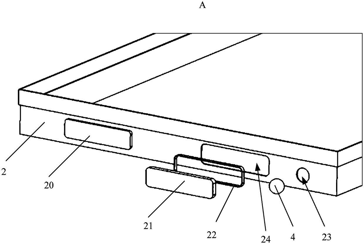
[0078] S2: welding the positive tab 33 of the laminated battery to the positive contact 20 of the lower case 2, and welding the negative tab 34 of the laminated battery to the negative contact 21 of the lower case 2;

[0079] S3: Fasten the upper shell 1 to the lower shell 2, and seal and weld the surroundings of the upper shell 1 and the lower shell 2;

[0...


PUM

PropertyMeasurementUnit
Wall thicknessaaaaaaaaaa

Abstract

The invention discloses a battery cell, electronic equipment and a battery cell package method. The battery cell comprises a shell and a battery core, wherein the shell comprises a steel lower shell and a steel upper shell, insulation layers are arranged on surfaces of the upper shell and the lower shell, the lower shell and the upper shell are hermetically connected by welding to form a sealing cavity, a positive contact sheet and a negative contact sheet are arranged on the shell, the battery core is a laminated battery core, the laminated battery core is fixed in the sealing cavity, and a positive tab and a negative tab of the lamination battery core are respectively connected with the positive contact sheet and the negative contact sheet. The battery cell can be applied to the field ofthe electronic equipment; by matching of the steel shells and the lamination battery core, the battery core can be in various shapes and various sizes, various complicated installation spaces of theelectronic equipment can be adapted, so that maximum capacity of the battery cell is achieved; and the battery cell is high in strength of integral structure and is difficult to deform and get failure, and the battery cell is safe and reliable to use and can be repeatedly used after disassembly.

Description

technical field [0001] The invention relates to the field of electronic equipment, in particular to an electric core, electronic equipment including the electric core and a packaging method for the electric core. Background technique [0002] Mobile phones have become an indispensable electronic product in people's lives. With the development of mobile phones, mobile phone batteries have also experienced several development stages. [0003] The first stage is the aluminum shell cell. The shell is a square shape made of aluminum by stamping, and the core is formed by rolling the core. The disadvantage is: because the shell is formed by stamping from aluminum, affected by the amount of deformation and material of the aluminum, the size cannot be made large enough, especially in the length direction, which causes the size of the battery cell to be limited, and the capacity of the battery cell cannot be made enough Big. [0004] The second stage is the soft package battery, wh...

Claims


Application Information

Patent Timeline
IPC IPC(8): H01M2/02H01M2/34H01M10/04H01M50/116H01M50/119H01M50/124H01M50/133H01M50/55H01M50/557H01M50/572H01M50/588H01M50/593
CPCH01M10/0436H01M2220/30H01M50/557H01M50/55H01M50/593H01M50/119H01M50/588H01M50/133H01M50/124Y02E60/10H01M50/578H01M50/159H01M50/134H01M50/169Y02P70/50H01M50/15H01M50/186H01M50/262H01M50/184H01M50/325
Inventor 张立群郭永锋
Owner XIAN ZHONGXING NEW SOFTWARE
Why Eureka
Try Eureka