Circular pipe weld joint automatic grinding device

A driving device, round tube technology, applied in auxiliary devices, grinding machines, welding equipment, etc., can solve the problems of difficult splicing welds, difficult automatic grinding of round tube splicing welds, and harsh grinding environments, so as to avoid grinding errors. The harm of people, the realization of unattended work, the good effect of polishing

Inactive Publication Date: 2018-06-29
SHANDONG SICHUANG ROBOT TECH CO LTD
View PDF8 Cites 16 Cited by
  • Summary
  • Abstract
  • Description
  • Claims
  • Application Information

AI Technical Summary

Problems solved by technology

In order to ensure the performance of the round pipe splicing and the spraying effect, the weld seam needs to be polished, and it is more difficult to polish the multi-bend round pipe splicing weld seam
Manual grinding mainly has the following disadvantages: first, the labor intensity of workers is high and the efficiency is low, and large-scale operations cannot be realized; second, the grinding quality is unstable and the surface shape is poor; third, the grinding control is not precise, and it is difficult to form a unified specification
In particular, the grinding environment is relatively harsh, and dust, noise, and flying debris are extremely harmful to the grinding workers.
[0003] At present, the existing automatic grinding equipment for round pipe welds has relatively single functions, poor precision and poor adaptability, and it is difficult to achieve automatic grinding for multi-bend round pipe welding seams
Grinding is realized by using a finished six-joint industrial robot, and its attached force control device, precise positioning device and displacement device result in high equipment cost and low efficiency.

Method used


Image

  • Circular pipe weld joint automatic grinding device
  • Circular pipe weld joint automatic grinding device
  • Circular pipe weld joint automatic grinding device

Examples


Embodiment Construction

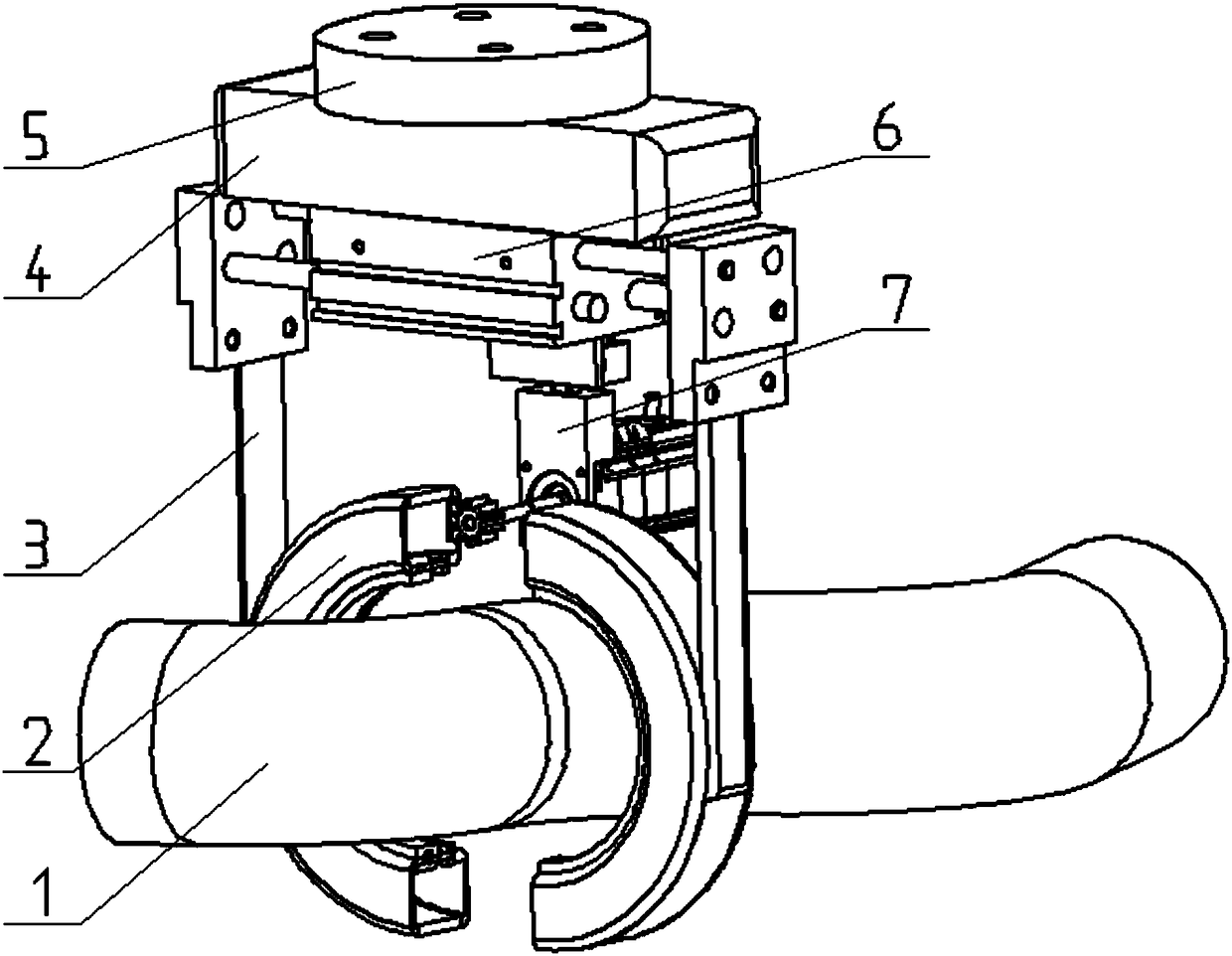
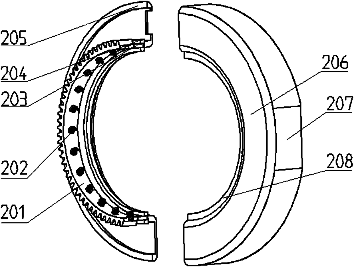
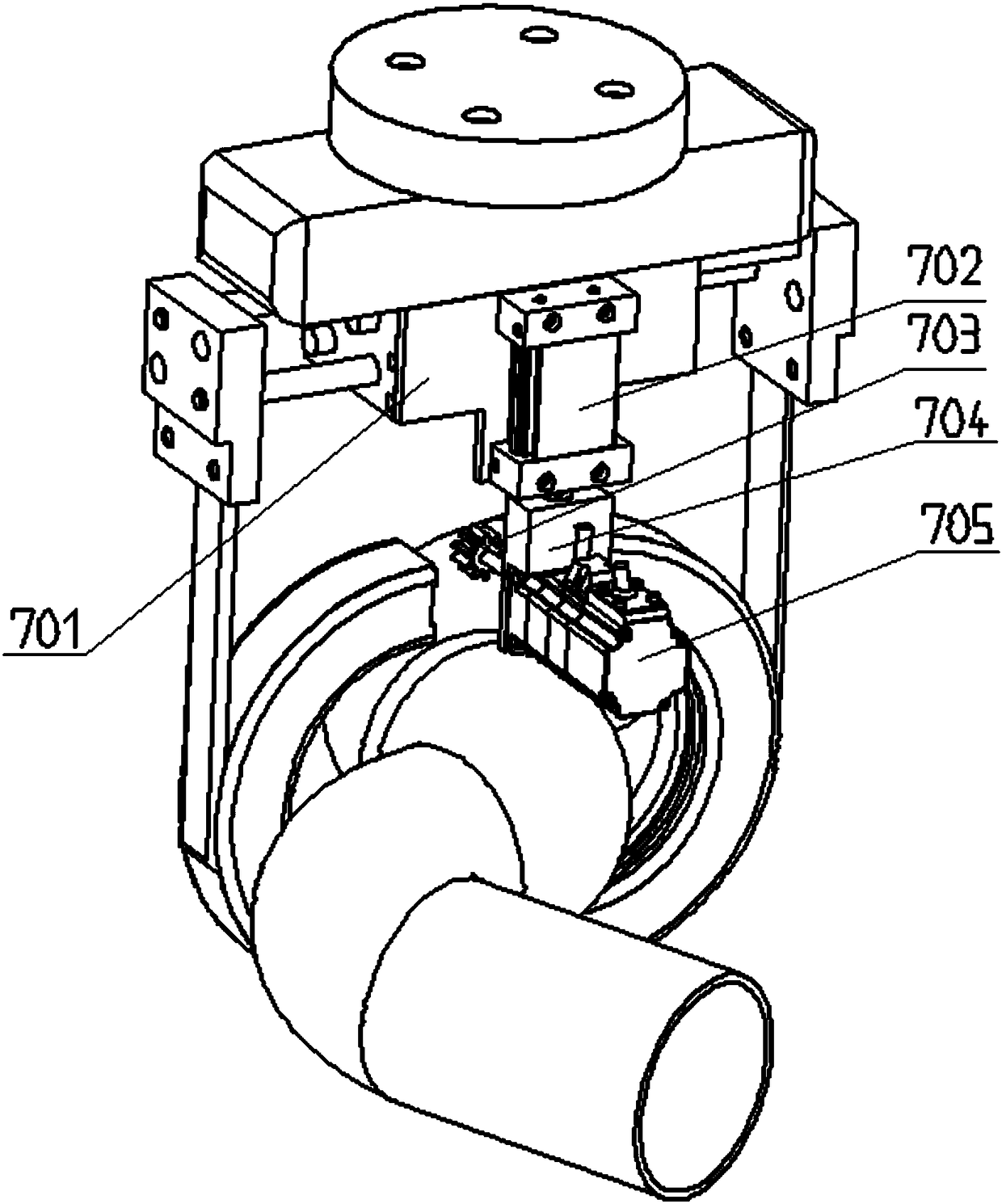
[0013] An automatic grinding device for a round pipe weld is composed of a round pipe 1, a grinding device 2, a support arm 3, a controller 4, a mounting flange 5, a wide air claw 6 and a driving device 7. The grinding device 2 includes a semi-circular ring gear 201, a spring 202, a slider 203, a sliding guide rail 204, a rear cover 205, a front cover 206, a side cover 207, and a grinding material 208, and the drive device 7 includes a cylinder mounting plate 701, a thin cylinder 702 , gear 703, motor fixing seat 704 and servo motor 705; the mounting flange 5 is fixed to the controller 4, the wide air claw 6 is installed under the controller 4, and the side of the cylinder mounting plate 701 on the driving device 7 is installed on the controller 4, the other side is equipped with a thin air cylinder 702, the servo motor 705 is connected with the thin air cylinder 702 through the motor holder 704, the gear 703 is installed on the main shaft of the servo motor 705, and the suppor...


PUM


Abstract

The invention discloses a circular pipe weld joint automatic grinding device and belongs to the field of grinding automatic equipment. The device is composed of a circular pipe, a grinding unit, supporting arms, a controller, a mounting flange, a wide gas claw and driving unit. The mounting flange is fixed to the controller. The wide gas claw is mounted under the controller. One side of a cylindermounting plate on the driving unit is mounted on the back side of the controller, and a thin cylinder is mounted on the other side of the cylinder mounting plate. A servo motor is connected with thethin cylinder through a motor fixing seat. A gear is mounted on a spindle of the servo motor. The supporting arms are mounted on paws on the two sides of the wide gas claw. Side covers in the grindingunit are connected with the supporting arms correspondingly. A front cover and a rear cover are mounted on the front and rear sides of the side covers correspondingly. A sliding guide rail is mountedon the rear cover. A semicircular gear ring is mounted on the sliding guide rail through a sliding block. Springs are mounted on the inner side of the semicircular gear ring, and a grinding materialis fixed through the springs. The circular pipe is fixed and all positions of a weld joint are exposed. Through the grinding device, the circular pipe splicing weld joint can be ground automatically.

Description

technical field [0001] The invention relates to an automatic grinding device for welded seams of round pipes, specifically a device that uses wide-type air claws and servo motors to drive gears, semi-circular ring gears and grinding materials to automatically grind the welded seams of round pipes, and belongs to the field of automatic grinding equipment . Background technique [0002] The splicing of round pipes is generally done by welding, and the surface of the spliced ​​weld after welding is not smooth and there are oxide scales and welding slag. In order to ensure the performance of the round pipe splicing and the spraying effect, the weld seam needs to be polished, and it is more difficult to polish the multi-bend round pipe splicing weld seam. Manual grinding mainly has the following disadvantages: first, the labor intensity of workers is high and the efficiency is low, and large-scale operations cannot be realized; second, the grinding quality is unstable and the su...

Claims


Application Information

Patent Timeline
Patent Type & Authority Applications(China)
IPC IPC(8): B24B27/033B23K37/08
CPCB24B27/033B23K37/08
Inventor 石运伟魏立凯杨继成苏春雷孙骥杨春清李诚欧欣东高进强
Owner SHANDONG SICHUANG ROBOT TECH CO LTD
Why Eureka
Try Eureka