
Range extender control system and method

A control method and a technology of a range extender, which are applied in engine-driven traction, battery/battery traction, electric vehicles, etc., can solve the problem of untimely speed response, complex working conditions, and failure to provide engine and generator speed and torque decoupling control to achieve reliable work and improve control accuracy

Inactive Publication Date: 2018-06-29
无锡增程电子科技有限公司
View PDF8 Cites 20 Cited by
  • Summary
  • Abstract
  • Description
  • Claims
  • Application Information

AI Technical Summary

Problems solved by technology

[0006] 1. With the application of electric vehicle systems becoming more and more extensive and the working conditions becoming more and more complex, the power requirements of the vehicle system for the range extender are also becoming more and more diverse. The existing technology fails to provide different forms The processing strategy of the range extender control system when the power is requested
[0007] 2. In the range extender system, the engine and the generator work through a mechanical connection, and the existing technology fails to provide decoupling control of the speed and torque of the engine and generator
[0008] 3. The existing technology only obtains the operating speed and torque of the range extender based on the fuel consumption characteristics of the engine, and fails to comprehensively and effectively consider the characteristics of engine emissions, noise and generator efficiency
[0009] 4. The existing technology does not provide protection and treatment measures under the working conditions such as overload and untimely speed response during the power generation process of the range extender

Method used


Image

  • Range extender control system and method
  • Range extender control system and method
  • Range extender control system and method

Examples


Embodiment Construction

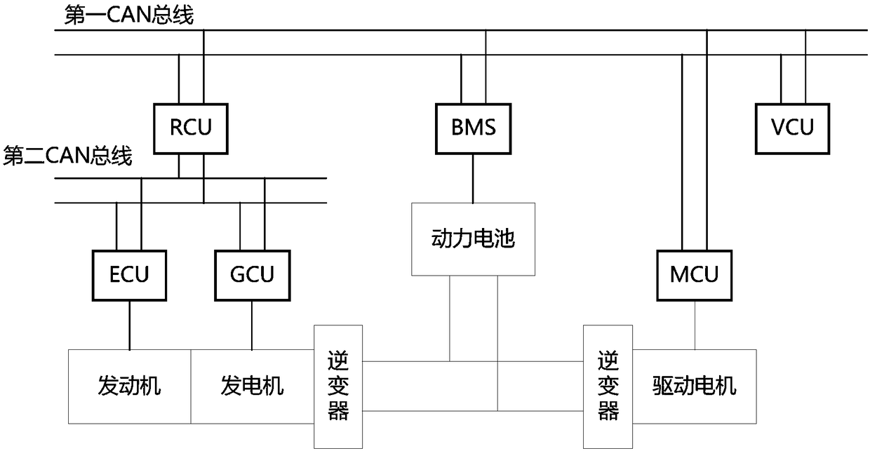
[0046] figure 1 It is a schematic diagram of the power system structure of an extended-range electric vehicle. There are two CAN networks in the figure. Specifically, it includes a first CAN bus and a second CAN bus. It also includes a range extender controller RCU connected to the first CAN bus, a power battery management system BMS, a drive motor controller MCU and a vehicle controller VCU. Also includes engine controller ECU and generator controller GCU. The range extender controller is connected to the engine controller ECU and the generator controller GCU of the range extender through the RCU through the second CAN bus.

[0047] The engine controller ECU is connected to control the engine, the generator controller GCU is connected to control the generator, and the drive motor controller MCU is connected to control the drive motor. The power battery is connected to the generator through the inverter. The power battery is connected to the drive motor through an inverte...


PUM


Abstract

The invention discloses a range extender control system and method. In the control system, an output end of a generated power demand module is connected to an input end of a state management module and an input end of an engine input power demand module. An output end of the state management module is connected with an input end of an engine control module and an input end of a power generator control module. An output end of an engine output power demand module is connected to the input end of the engine control module and the input end of the power generator control module. An output end ofa range extender working mode selecting module is connected to the input end of the engine control module and the input end of the power generator control module. Power generation requirements of different forms can be received and responded to according to the requirements of a vehicle system, and meanwhile the application occasions of an electric vehicle range extender are enlarged by flexibly adding and deleting sub-modules in a vehicle energy request queue.

Description

technical field [0001] The invention relates to a control system and a control method, in particular to a control system and a control method for a range extender. Background technique [0002] Chinese patent CN201710535437 provides an optimal control method for an electric vehicle range extender. The purpose of this patent is to design a multi-stage power following control method suitable for the operation of urban extended-range electric vehicles. The technical means and effect achieved in this patent are: design the engine speed according to the required power, select N operating points on the optimal fuel consumption curve for constant speed operation, and adjust the torque of the range extender generator to Make the actual output power value of the range extender follow the current power demand, and at the same time determine the current demand value of the range extender in the static coordinate system, and determine the driving signal of the generator power switch by...

Claims


Application Information

Patent Timeline
IPC IPC(8): B60L11/12B60W10/06B60W10/08B60W20/10B60L50/15
CPCB60L50/61B60W10/06B60W10/08B60W20/10B60W2710/0666B60W2710/083Y02T10/62Y02T10/70
Inventor 胡川杭勇朱晓明
Owner 无锡增程电子科技有限公司
Features
  • Generate Ideas
  • Intellectual Property
  • Life Sciences
  • Materials
  • Tech Scout
  • Unparalleled Data Quality
  • Higher Quality Content
  • 60% Fewer Hallucinations
Learn More