Fabricated concrete-filled steel tube combination column and splicing method

A technology for CFST column and CFST, which is applied to columns, piers, pillars, etc., can solve the problems of unfavorable promotion and application of CFST columns, the corrosion resistance of steel tubes is not as good as concrete, and the fire resistance is not as good as concrete, etc. Bearing capacity and deformation capacity, the effect of improving flexural rigidity

Pending Publication Date: 2018-06-29
HUAQIAO UNIVERSITY
View PDF7 Cites 3 Cited by
  • Summary
  • Abstract
  • Description
  • Claims
  • Application Information

AI Technical Summary

Problems solved by technology

However, the fire resistance of steel pipes is not as good as that of concrete, which will have an adverse effect on the components in a fire environment; the corrosion resistance of steel pipes is also not as good as that of concrete, which will increase its later maintenance costs, which is not conducive to the further popularization and application of steel pipe concrete columns

Method used


Image

  • Fabricated concrete-filled steel tube combination column and splicing method
  • Fabricated concrete-filled steel tube combination column and splicing method
  • Fabricated concrete-filled steel tube combination column and splicing method

Examples


Embodiment 1

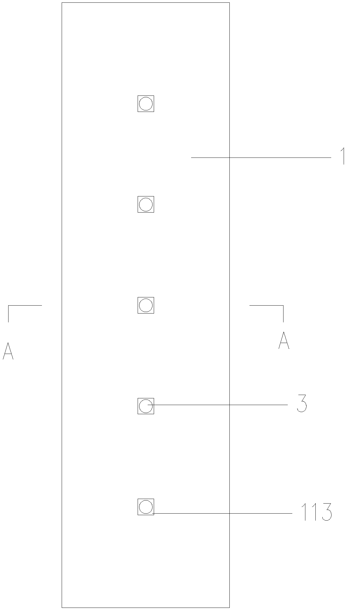
[0030] Please check Figure 1 to Figure 4 , a prefabricated steel tube concrete composite column, comprising a steel tube concrete prefabricated part 1 and a screw rod 2.

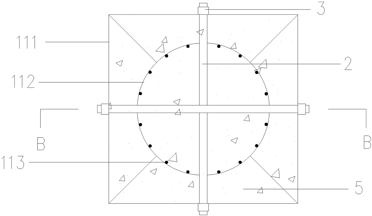
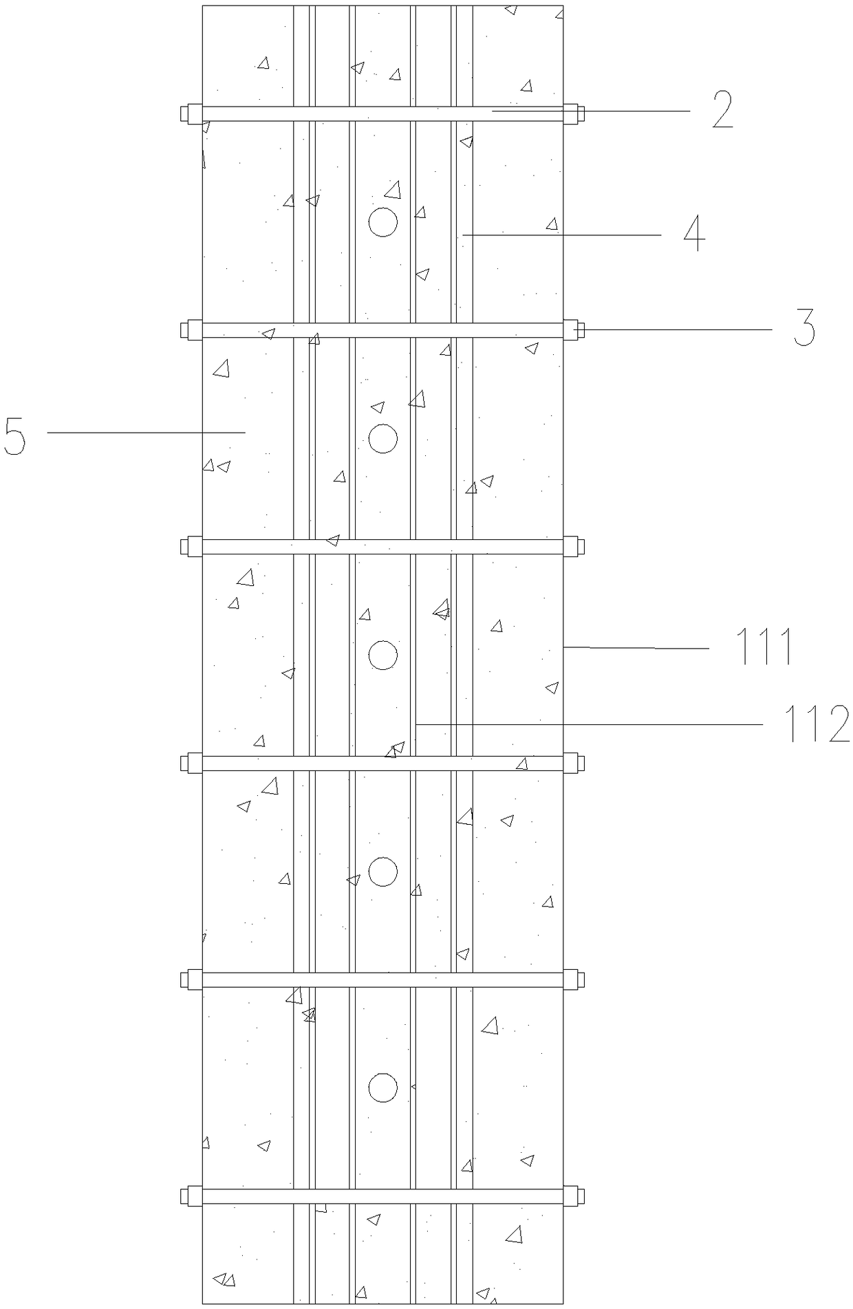
[0031] In this embodiment, the concrete-filled steel tube prefabricated part 1 is surrounded and spliced ​​by two concrete-filled steel tube columns 11 to form a whole. After splicing, the curved steel plate 112 constitutes the inner wall of the steel pipe concrete prefabricated part, and the rectangular steel plate 111 constitutes the outer wall of the steel pipe concrete prefabricated part. Such as figure 2 and Figure 4 As shown, the arc-shaped steel plates of the two concrete-filled steel pipe columns 11 have a half circumference. After being enclosed and spliced, the inner wall section of the steel pipe concrete composite column is circular, and the outer wall section of the steel pipe concrete composite column is square. .

[0032] The rectangular steel plate 111 and the curved steel plate 112 ar...

Embodiment 2

[0043] Such as Figure 5 As shown, the difference between this embodiment and Embodiment 1 is that the concrete-filled steel pipe prefabricated part is surrounded by four concrete-filled steel pipe columns 11 and spliced ​​into a whole, and the arc-shaped steel plates 112 of the four steel pipe concrete columns each have four One-half of the circumference, after enclosing and splicing, the cross section of the inner wall of the steel pipe concrete composite column is circular, and the cross section of the outer wall of the steel pipe concrete composite column is square.


PUM


Abstract

The invention discloses a fabricated concrete-filled steel tube combination column and a splicing method. The fabricated concrete-filled steel tube combination column comprises a concrete-filled steeltube prefabricated part which is spliced into a whole by means of being defined by at least two concrete-filled steel tube columns, and after defining and splicing, the section of the concrete-filledsteel tube prefabricated part is externally square and internally circle. Through holes are formed in a rectangular steel plate and an arc-shaped steel plate, the rectangular steel plate and the arc-shaped steel plate are formed through welding, and then reinforcements are welded to the internally-sunken side of the arc-shaped steel plate. The multiple concrete-filled steel tube columns forms theconcrete-filled steel tube prefabricated part with the section being externally square and internally circle in defined and spliced modes, and then screws are connected into the through holes formedin the rectangular steel plate and the arc-shaped steel plate in an inserted mode to be fixed. A pouring material is injected into the concrete-filled steel tube prefabricated part. According to the fabricated concrete-filled steel tube combination column, the constraint effect of internal circular steel tubes on the pouring material in a core area can be ensured, and the advantage of the rectangular section on building arrangement can also be developed.

Description

technical field [0001] The technical field of the data building structure of the present invention, in particular relates to a fabricated steel pipe concrete composite column and a splicing method. Background technique [0002] As a new type of high-efficiency composite member, the CFST column has been more and more widely used in practical engineering because it can give full play to the material properties of both steel and concrete. At present, the common forms of CFST columns include rectangular CFST columns and circular CFST columns. Compared with circular CFST columns, rectangular CFST columns are more suitable for building layout and improve space utilization efficiency, but the steel pipes in rectangular CFST columns have poor confinement effect on concrete, which restricts its application to a certain extent. In addition, steel pipes in CFST columns can be used as templates for pouring inner concrete, which brings convenience to construction. However, the fire res...

Claims


Application Information

Patent Timeline
Patent Type & Authority Applications(China)
IPC IPC(8): E04C3/32E04C3/34E04B1/58
CPCE04B1/5825E04C3/32E04C3/34
Inventor 高鹏林凡方膨膨胡红松
Owner HUAQIAO UNIVERSITY
Why Eureka
Try Eureka