Air energy low-temperature liquefied gas pump-free filling system
A low-temperature liquefied gas, filling system technology, applied in pipeline systems, gas/liquid distribution and storage, fluid processing, etc., can solve the problems of large investment, consumption, limited life and so on
- Summary
- Abstract
- Description
- Claims
- Application Information
AI Technical Summary
Problems solved by technology
Method used
Image
Examples
Embodiment 1
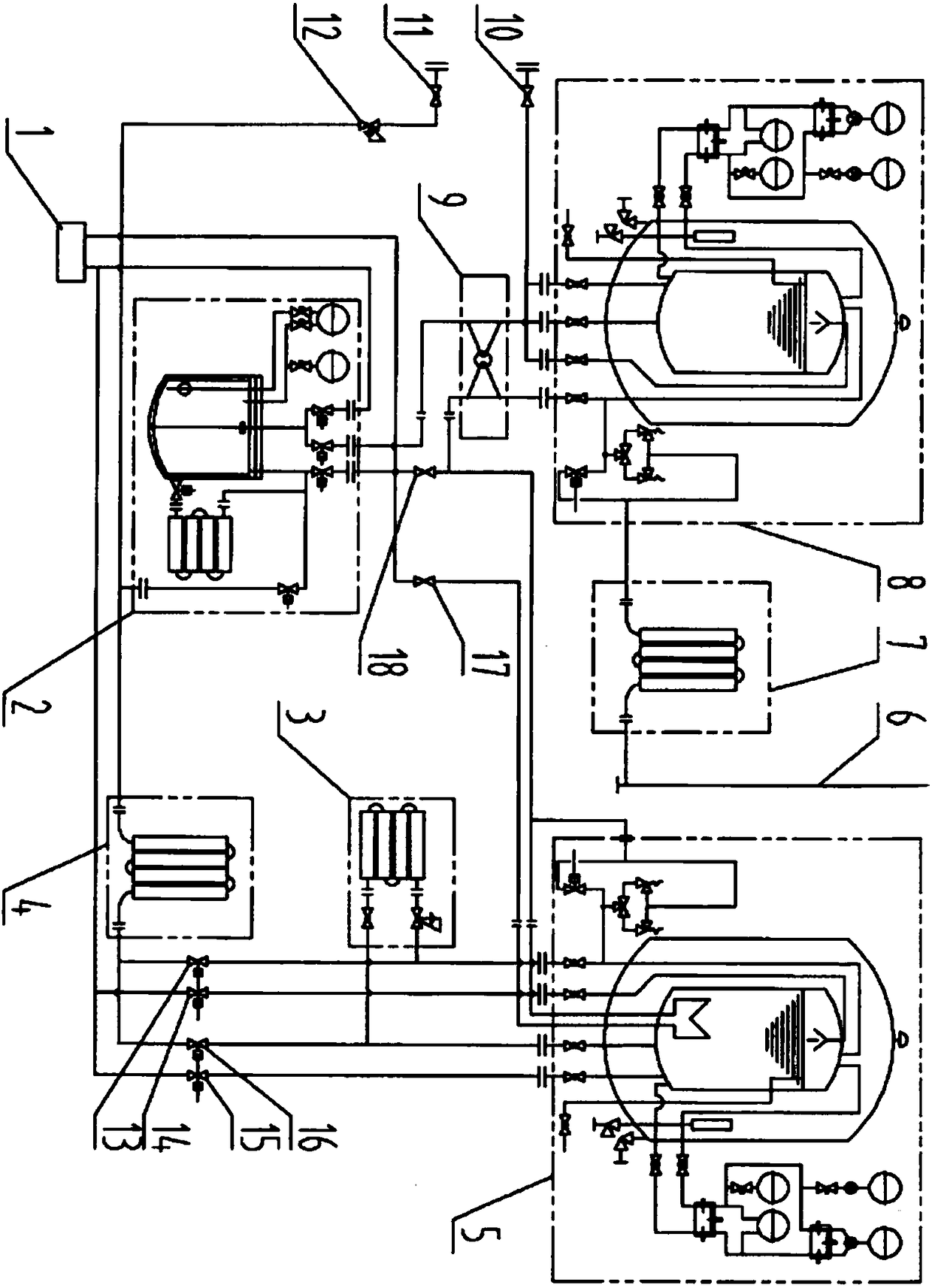
[0060] Embodiment 1: as figure 1 As shown, an air-energy low-temperature liquefied gas pumpless filling system includes a gas filling machine (1), a transfer tank (2), a supercharger (3), a temperature-increasing vaporizer (4), a high-pressure low-temperature storage tank ( 5), vent pipe (6), EAG vaporizer (7), low-pressure low-temperature storage tank (8), low-saturation heat exchanger (9), etc.
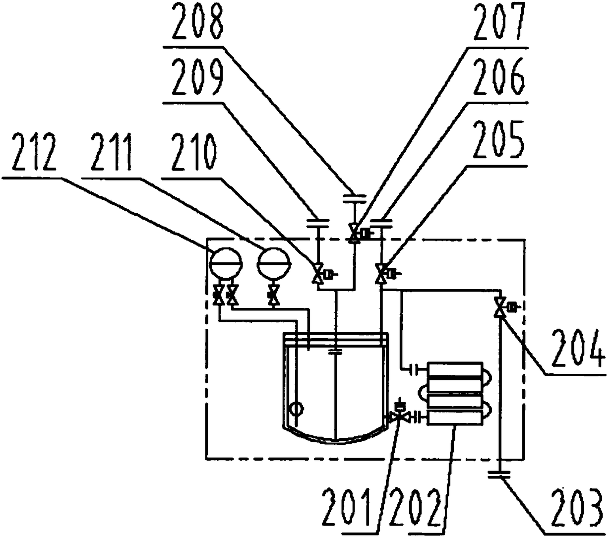
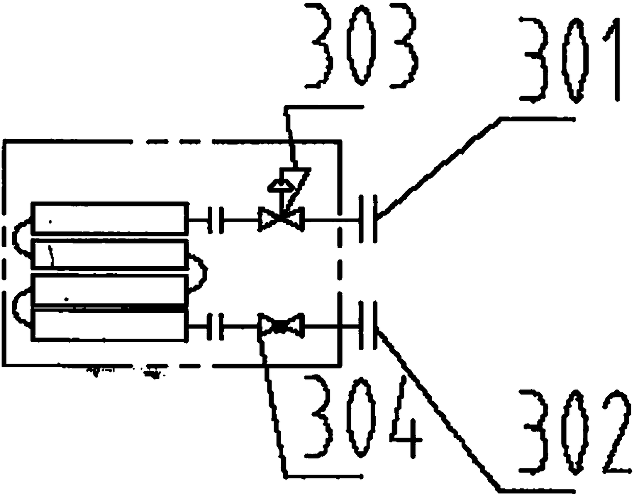
[0061] The transfer tank (2) is an external cold-preservation container, and the transfer tank (2) is the core to realize the conversion of low-temperature and low-pressure liquefied gas to high-pressure, that is, transfer low temperature from the low-pressure and low-temperature storage tank (8) to the high-pressure and low-temperature storage tank (5). The liquefied gas is realized through the transfer tank (2). The transfer tank (2) is at least provided with four openings: a transfer tank boost port (203), a transfer tank pressure relief port (206), a transfer tank liquid inlet ...
Embodiment 2
[0075] Embodiment 2: All gasifiers in the system (such as: booster (3), temperature-increasing gasifier (4), EAG gasifier (7), transfer tank booster (202), etc.) can be empty The warm type absorbs air energy to heat and pressurize; it can also be heated by steam or other heat media to provide energy to heat and pressurize. Others are with embodiment 1.
Embodiment 3
[0076] Embodiment 3: The transfer tank (2) can be connected in parallel with multiple corresponding interfaces, such as connecting the liquid outlets (209) of each transfer tank together and then connecting to the system; connecting the liquid inlets (208) of each transfer tank together Connect to the system again; connect the booster ports (203) of the transfer tanks together and then connect to the system; connect the pressure relief ports (206) of the transfer tanks together and then connect to the system. The working steps of each group of transfer tanks (2) are carried out alternately. Others are with embodiment 1.
PUM
 Abstract
Description
Claims
Application Information
 - R&D
- Intellectual Property
- Life Sciences
- Materials
- Tech Scout
- Unparalleled Data Quality
- Higher Quality Content
- 60% Fewer Hallucinations
Browse by: Latest US Patents, China's latest patents, Technical Efficacy Thesaurus, Application Domain, Technology Topic, Popular Technical Reports.
© 2025 PatSnap. All rights reserved.Legal|Privacy policy|Modern Slavery Act Transparency Statement|Sitemap|About US| Contact US: help@patsnap.com


