FPGA-based fiber end face testing method and system

An optical fiber end face and detection method technology, applied in the directions of light guides, optics, optical components, etc., can solve the problems of long accumulation time, long welding time, time consumption, etc., and achieve the effect of accurate search results and improved processing speed.

Inactive Publication Date: 2018-06-29
INNO INSTR (CHINA) INC
View PDF10 Cites 1 Cited by
  • Summary
  • Abstract
  • Description
  • Claims
  • Application Information

AI Technical Summary

Problems solved by technology

[0004] However, this method has the following defects: the software needs to wait blindly for at least two frames of complete image refresh time before reading the image data of the camera each time, and it also takes time to read a complete frame of camera image

Method used


Image

  • FPGA-based fiber end face testing method and system
  • FPGA-based fiber end face testing method and system
  • FPGA-based fiber end face testing method and system

Examples


Embodiment Construction

[0043] In order to make the above objects, features and advantages of the present invention more comprehensible, specific implementations of the present invention will be described in detail below in conjunction with the accompanying drawings.

[0044]In the following description, numerous specific details are set forth in order to provide a thorough understanding of the present invention. However, the present invention can be implemented in many other ways different from those described here, and those skilled in the art can make similar extensions without violating the connotation of the present invention, so the present invention is not limited by the specific implementations disclosed below.

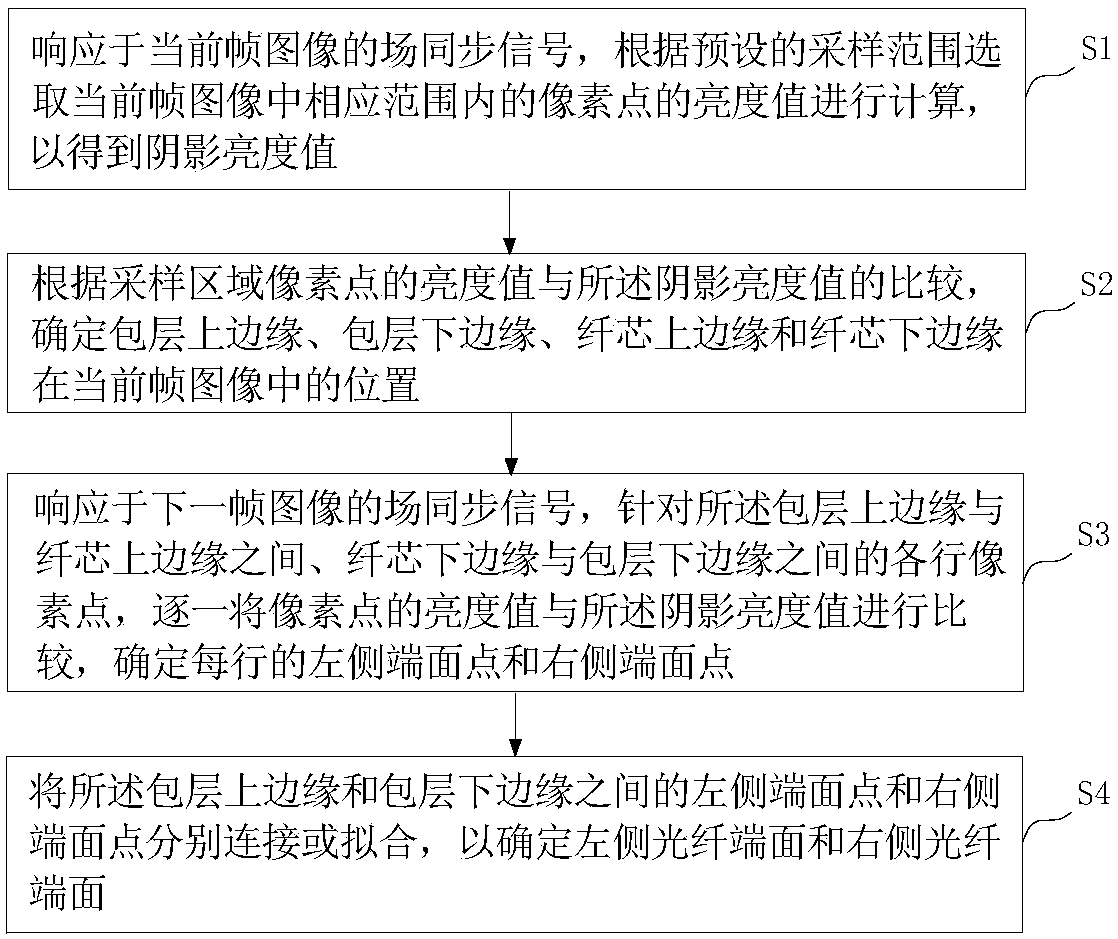
[0045] In one embodiment, see figure 1 , based on the FPGA (Field-Programmable Gate Array, Field Programmable Gate Array) optical fiber end-face detection method, the camera is mounted on the FPGA, and each frame of image taken is transmitted to the FPGA in real time, and directly pr...


PUM


Abstract

The invention provides an FPGA-based fiber end face testing method and system. A camera is mounted on FPGA, and transmits every frame of the shot image into the FPGA in real time; the FPGA executes the following steps: responding to a field synchronizing signal of current-frame image, selecting the brightness values of pixel points in current-frame image according to a sampling range, and calculating to obtain a shadow brightness value; comparing the brightness values of the pixel points in the sampling area with the shadow brightness value, to determine the positions of the upper and lower edges of the cladding and the upper and lower edges of the fiber core, in the current-frame image; responding to a field synchronizing signal of next-frame image; comparing the brightness values of thepixel points on each row between the upper edge of the cladding and the upper edge of the fiber core and between the lower edge of the fiber core and the lower edge of the cladding, with the shade brightness value one by one, to determine the left-side end face point and the right-side end face point on each row; and connecting or fitting the left-side end face points and the right-side end face points between the upper edge and the lower edge of the cladding respectively, to determine the end face.according to the invention, the end face can be quickly found to reduce time consumption.

Description

technical field [0001] The invention relates to the technical field of optical fiber image processing, in particular to an FPGA-based optical fiber end face detection method and system. Background technique [0002] The optical fiber fusion splicer is a precision instrument that melts the end faces of two optical fibers with a high-voltage arc, and at the same time, uses a high-precision motion mechanism to gently advance the two optical fibers into one, so as to realize the coupling of the optical fiber mode field. During the advancing process, it is necessary to continuously read the position information of the end face of the optical fiber to determine the next step of the motor. [0003] At present, the position of the fiber end face on the image is generally determined by the following method: the software needs to wait blindly for at least two frames of camera image refresh time, and then read a certain frame stored in DDR (Dynamic Random Access Memory) through the EBI...

Claims


Application Information

Patent Timeline
IPC IPC(8): G02B6/255G06T7/00
CPCG02B6/2551G02B6/2555G06T7/0004G06T2207/30108
Inventor 李楚元
Owner INNO INSTR (CHINA) INC
Why Eureka
Try Eureka