Time mark alignment method for redundancy system data acquisition

A technology of system data and redundancy, applied in general control systems, control/regulation systems, instruments, etc., can solve problems such as low time stamp accuracy, out-of-step, and influence on data analysis effects, so as to ensure real-time performance and accuracy, Improved reliability, easy-to-achieve effects

Inactive Publication Date: 2018-06-29
CHENGDU AIRCRAFT DESIGN INST OF AVIATION IND CORP OF CHINA
View PDF9 Cites 8 Cited by
  • Summary
  • Abstract
  • Description
  • Claims
  • Application Information

AI Technical Summary

Problems solved by technology

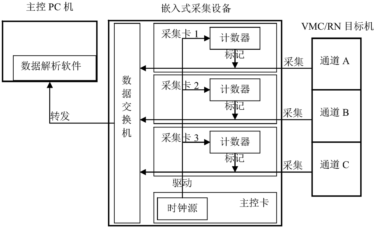
If the heartbeat value of the VMC / RN target machine is directly used as the time scale for channel data alignment, when the VMC itself is already in an out-of-sync (non-synchronized) state, the data aligned on the time axis will not really occur simultaneously. It is impossible to restore the real timing of the system; the flight test interface (hereinafter referred to as FTI) of the current aircraft management system uses the time stamp of the main control PC to mark the data packets collected by each channel, but is subject to the non-real-time operation of the PC windows System, the timing mark operation is greatly affected by other processes, and the time stamp precision generated by the software is low (microsecond level), misalignment or missynchronization still occurs during actual use, which seriously affects the effect of data analysis

Method used


Image

  • Time mark alignment method for redundancy system data acquisition

Examples


Embodiment 1

[0016] Example 1: Resynchronization test of each redundant channel after VMC restarts 1

[0017] The embedded acquisition device chooses to observe the heartbeat value of the VMC operating system. After starting data acquisition, power off all channels of VMC, and then power on VMC A, B, and C in turn (within 3 seconds). After stopping the acquisition, use the data analysis software to draw The heartbeat value of the operating system. After confirming the asynchronous power-on operation of the VMC, the on-board software starts synchronization, and the heartbeat value of the three-channel VMC restarts to increase synchronously.

[0018] Because the present invention is realized based on CPLD / FPGA hardware resources and embedded real-time software in the embedded acquisition device, it effectively avoids the limitations of using the target machine to generate time stamps and must ensure the synchronization of the target machine itself.

Embodiment 2

[0019] Example 2: Resynchronization test of each redundant channel after VMC restarts 2

[0020] The embedded acquisition device chooses to observe the heartbeat value of the VMC operating system. After starting data acquisition, power off all channels of VMC, and then power on VMC A, B, and C in turn (interval 5 seconds). After stopping the acquisition, use the data analysis software to draw the operation System heartbeat value, after confirming VMC asynchronous power-on operation, because the asynchronous degree exceeds the on-board software startup synchronization tolerance, the three-channel VMC heartbeat value still increases asynchronously.

[0021] Because the present invention is based on the CPLD / FPGA hardware resources and embedded real-time software in the embedded acquisition device, it effectively avoids using the target machine to generate time scales. When the target machine itself is out of sync, the curve is drawn as three channels synchronously.

Embodiment 3

[0022] Embodiment 3: Mode switching test from VMC PBIT to control management

[0023] The embedded acquisition device selects and observes the VMC operating system system mode word. After starting data acquisition, press the PBIT switch to make VMC enter PBIT, and then press the PBIT switch again to make VMC exit PBIT mode and return to control management mode. After stopping the acquisition, draw with data analysis software The system mode word changes, after confirming that the VMC exits PBIT asynchronously (asynchronously becomes the initialization mode), after the on-board software starts the synchronization, the three-channel VMC system mode word changes to the control management mode at the same time.

[0024] Because the present invention is based on the CPLD / FPGA hardware resources and embedded real-time software in the embedded acquisition device, it effectively avoids the use of the main control PC to generate the time scale, and is subject to the influence of other p...


PUM


Abstract

The invention belongs to the technical field of aircraft engineering application and relates to a time mark alignment method for redundancy system data acquisition. The method comprises the followingsteps: a) sequentially connecting each acquisition card with a debugging interface of each redundancy VMC (Velocity Management Computer) or RN (Remote Node) target machine, as a data acquisition chain; b) setting a counter into a CPLD (Complex Programmable Logic Device) of each acquisition card, and by taking a counting value as a time maker, performing time sequence marking on an acquired targetmachine data packet; c) setting a 10MHz high-performance clock source in an FPGA (Field Programmable Gate Array) of a main control card, leading out through a hard wire, and synchronously driving allcounters in the step b); d) when real-time embedded software in the acquisition card receives target machine acquisition data each time, reading a time marking value generated in the step b), and transferring the time marking value and the acquisition data to a main control PC (Personal Computer); e) according to the time marking value, expanding and analyzing redundancy target machine data packets on a same time axis by analysis software of the main control PC according to the time marking value, thereby achieving the purpose of reducing real target machine time sequences.

Description

technical field [0001] The invention belongs to the technical field of aeronautical engineering applications, and relates to a time scale alignment method for data collection of a redundancy system. Background technique [0002] The WL-A aircraft management system adopts a redundancy architecture. After the aircraft management computer (hereinafter referred to as VMC) and the remote node (hereinafter referred to as RN) of each redundant channel collect data, they need to conduct analysis on the same time axis. Channel timescale alignment issues. If the heartbeat value of the VMC / RN target machine is directly used as the time scale for channel data alignment, when the VMC itself is already in an out-of-sync (non-synchronized) state, the data aligned on the time axis will not really occur simultaneously. It is impossible to restore the real timing of the system; the flight test interface (hereinafter referred to as FTI) of the current aircraft management system uses the time ...

Claims


Application Information

Patent Timeline
IPC IPC(8): G05B19/042
CPCG05B19/0423G05B2219/24215
Inventor 胡锐张军迟文明李渊饶晓孙吉洪
Owner CHENGDU AIRCRAFT DESIGN INST OF AVIATION IND CORP OF CHINA
Why Eureka
Try Eureka