Mode configuration/control method/system of electronic equipment, medium and electronic equipment
A technology of electronic equipment and mode configuration, which is applied in the direction of medical equipment, etc., can solve problems such as inability to distinguish calibration files and affect the quality of flat panel detector images, and achieve the effects of facilitating diagnosis, improving scalability, and improving recognition
- Summary
- Abstract
- Description
- Claims
- Application Information
AI Technical Summary
Problems solved by technology
Method used
Image

Examples
Embodiment 1
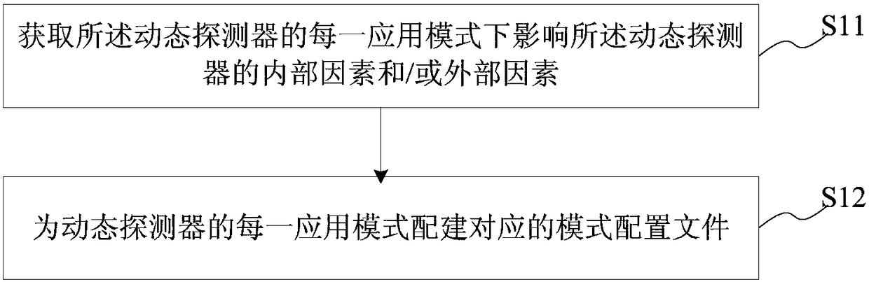
[0041] This embodiment provides a mode configuration method of an electronic device, the electronic device has at least two application modes; the mode configuration method of the electronic device includes:
[0042] Obtaining internal factors and / or external factors affecting the electronic device in each application mode of the electronic device;
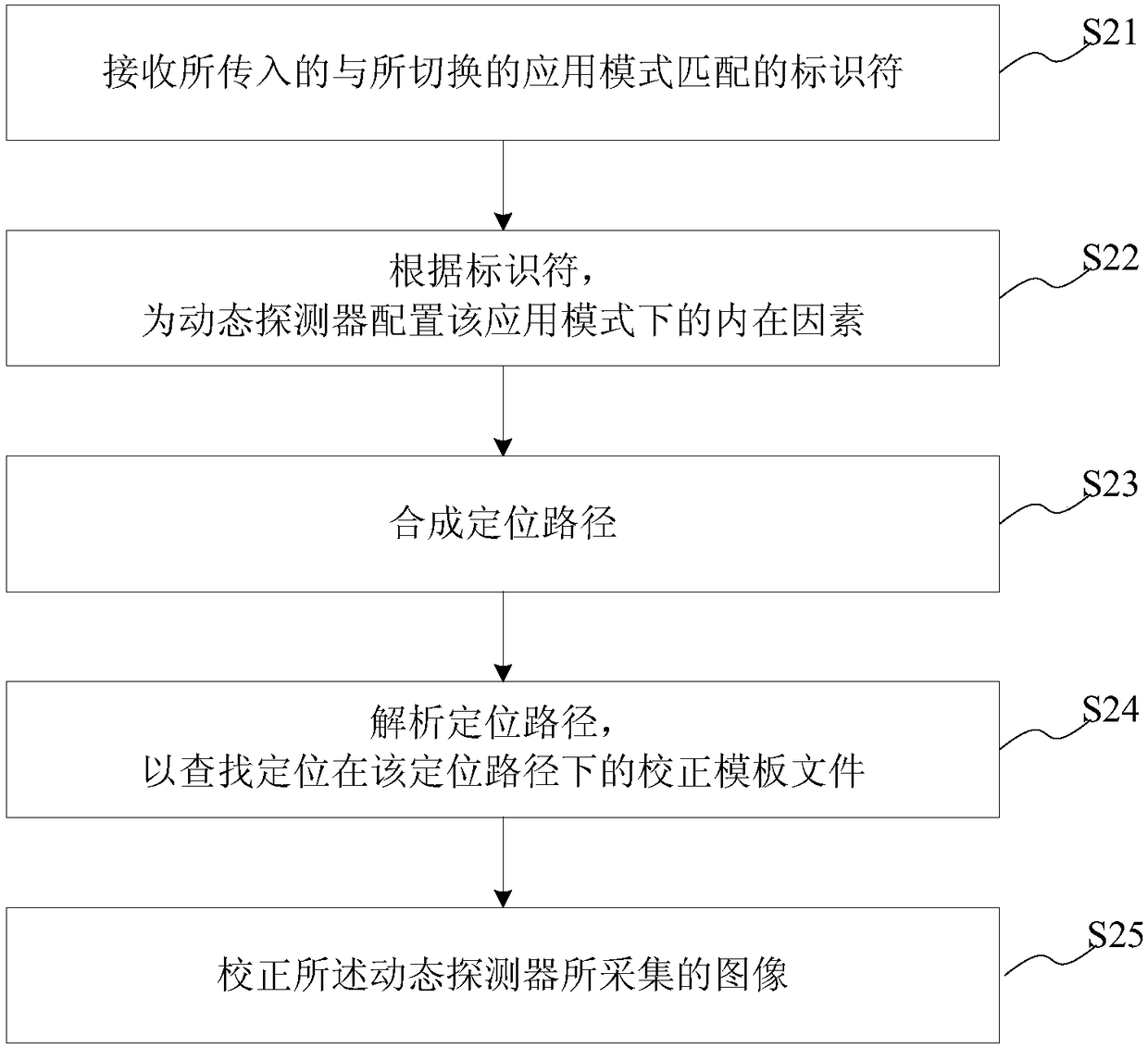
[0043] Configure a corresponding mode configuration file for each application mode of the electronic device; the mode configuration file includes internal factors, external factors and / or identifiers matching the application mode of the electronic device; the identifier It is used to synthesize a positioning path; the positioning path is used to locate corresponding correction template files in different application modes.
[0044] The mode configuration method of the electronic device provided by this embodiment will be combined with illustrations below. In this embodiment, the electronic device refers to a dynamic detector. Th...
Embodiment 2
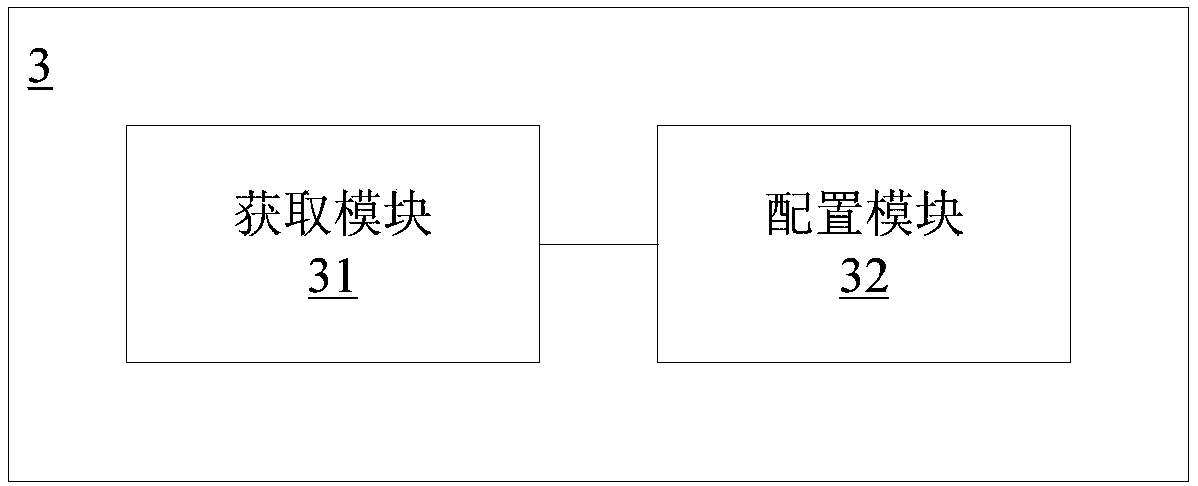
[0102] This embodiment provides a mode configuration system of an electronic device, the electronic device has at least two application modes; the mode configuration system of the electronic device includes:
[0103] An acquisition module, configured to acquire internal factors and / or external factors affecting the electronic device in each application mode of the electronic device;
[0104] A configuration module, configured to create a corresponding mode configuration file for each application mode of the electronic device; the mode configuration file includes internal factors, external factors and / or identifiers matching the application mode of the electronic device; The identifier is used to synthesize a positioning path; the positioning path is used to locate corresponding correction template files in different application modes.
[0105] This embodiment also provides a mode control system of an electronic device based on the mode configuration system of an electronic dev...
Embodiment 3
[0128] This embodiment provides an electronic device, and the electronic device includes: a processor, a memory, a transceiver, a communication interface, and a system bus; the memory and the communication interface are connected to the processor and the transceiver through the system bus and complete mutual communication, The memory is used to store the computer program, the communication interface is used to communicate with other devices, the processor and the transceiver are used to run the computer program, so that the electronic device executes the various steps of the mode configuration method of the electronic device as described above, and / or the electronic device Device mode control method
[0129] The system bus mentioned above may be a Peripheral Component Interconnect (PCI for short) bus or an Extended Industry Standard Architecture (EISA for short) bus or the like. The system bus can be divided into address bus, data bus, control bus and so on. For ease of repre...
PUM
 Abstract
Description
Claims
Application Information