X-band miniaturized cone-spiral antenna

An X-band and antenna technology, applied in the field of antennas, can solve the problems of increased antenna weight, large installation area, and high cost of antenna arrays, and achieve the effect of miniaturization, miniaturization design, and light weight

Active Publication Date: 2018-07-03
SHANGHAI AEROSPACE ELECTRONICS CO LTD +1
View PDF10 Cites 6 Cited by
  • Summary
  • Abstract
  • Description
  • Claims
  • Application Information

AI Technical Summary

Problems solved by technology

Using microstrip antennas or other antenna arrays can achieve this function, but the cost of antenna array weighting is too high, and it will increase the weight of the antenna, which does not meet the requirements of small satellites for lightweight antennas
The reflector antenna can also be used to assign beams, but its structure is bulky and the installation occupies a large area, which affects the use of limited satellite installation resources

Method used


Image

  • X-band miniaturized cone-spiral antenna
  • X-band miniaturized cone-spiral antenna
  • X-band miniaturized cone-spiral antenna

Examples


Embodiment Construction

[0016] The specific implementation manners of the present invention will be further described in detail below in conjunction with the accompanying drawings.

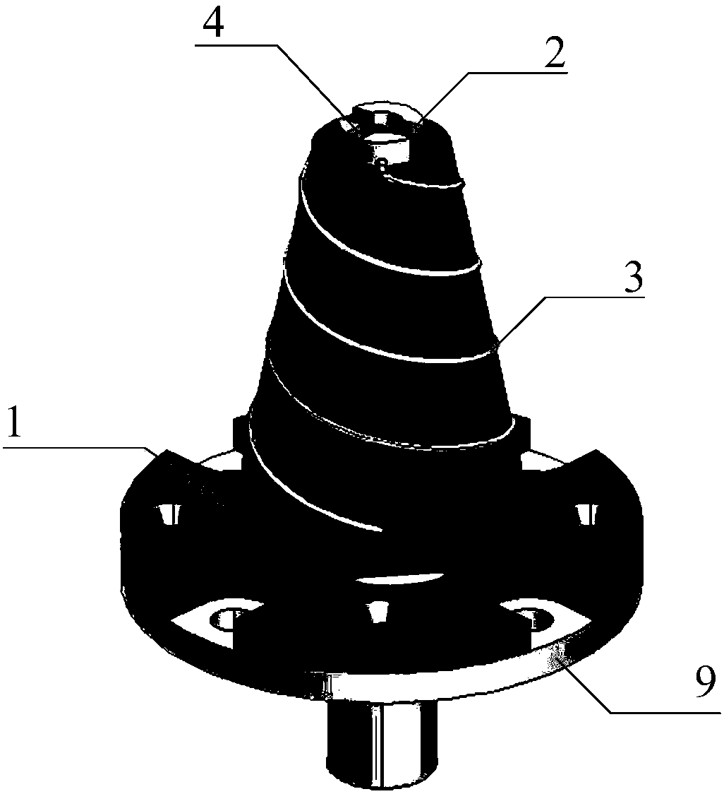
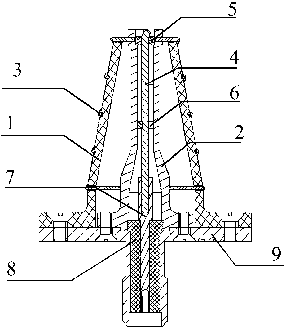
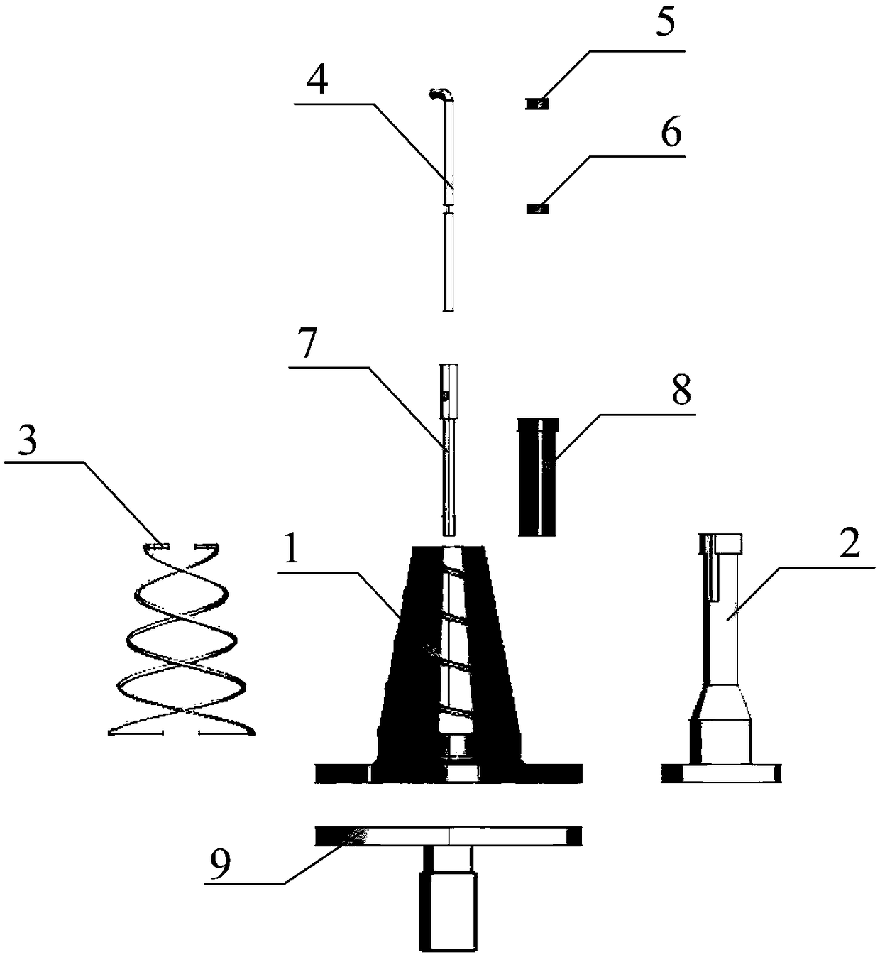
[0017] The X-band miniaturized conical-spiral antenna proposed by the invention is suitable for signal transmission of a small satellite X-band data transmission system. Such as figure 1 Shown is the schematic diagram of the three-dimensional structure of the present invention, figure 2 Shown is the sectional view of the present invention, image 3 Shown are each structural assembly of the present invention, combined figure 1 , figure 2 and image 3 , the X-band miniaturized cone-screw antenna of the present invention mainly includes a dielectric tube 1, an outer conductor 2, a metal helix 3, an inverted L-shaped inner conductor 4, a first dielectric column 5, a second dielectric column 6, a ferrule 7, and a core sleeve 8 and metal bottom plate 9.

[0018] The dielectric cylinder 1 is mainly composed of two parts...


PUM


Abstract

The invention provides an X-band miniaturized cone-spiral antenna which comprises a dielectric cylinder, an outer conductor, a metal spiral line, an inverted L-shaped inner conductor, a first dielectric pillar, a second dielectric pillar, an insertion core, a core sleeve and a metal base plate. The dielectric cylinder is a non-metallic cylinder with a hollow inner part. The outer conductor is a metal shell with a hollow internal part and is placed in the dielectric cylinder. The metal spiral line passes through the dielectric cylinder, and an upper end of the metal spiral line is connected toan outer wall of the outer conductor. The first dielectric pillar sleeves an outer part of the inverted L-shaped inner conductor and is fixed to a top L-shaped part, and the second dielectric pillar is fixed to a narrow groove of the inverted L-shaped inner conductor. The inverted L-shaped inner conductor is fixed in a hollow cylinder with a larger diameter at the upper end of the insertion core.The length of the core sleeve is same with that of a narrow cylinder at the lower end of the insertion core, the core sleeve sleeves the outer part of the narrow cylinder at the lower end of the insertion core, and an antenna feed structure is formed.

Description

technical field [0001] The invention belongs to the field of antennas and is suitable for data transmission of X-band radio frequency signals of small satellites such as microsatellites and pina satellites. Background technique [0002] The invention is an X-band data transmission antenna for a small satellite platform. Small satellites refer to artificial satellites with a mass of less than 1000kg, among which microsatellites refer to satellites with a mass of 10kg to 1000kg, and pina satellites refer to satellites with a mass of less than 10kg. With the development of technologies such as integrated multi-functional structure, space plug-and-play, integrated integrated electronics, and the innovation of satellite design ideas, the capabilities of small satellites continue to improve, and they are highly valued in the military, civilian, and commercial fields. Compared with large satellites, high-tech content, low cost, short manufacturing and launch cycles, and quick emer...

Claims


Application Information

Patent Timeline
Patent Type & Authority Applications(China)
IPC IPC(8): H01Q1/38H01Q1/36H01Q1/50H01Q1/28
CPCH01Q1/288H01Q1/36H01Q1/38H01Q1/50Y02D30/70
Inventor 蒋琪王小军沈鹏辛文莉
Owner SHANGHAI AEROSPACE ELECTRONICS CO LTD
Why Eureka
Try Eureka