
Oil-well low-liquid-producing high-water-containing oil-water-two-phase-flow flow measuring method

A flow measurement, water oil and water technology, applied in the direction of measurement, earthwork drilling, wellbore/well components, etc., to achieve the effects of improving water holdup measurement resolution, sensitive capture, and increasing current density intensity

Inactive Publication Date: 2018-07-06
TIANJIN UNIV
View PDF8 Cites 15 Cited by
  • Summary
  • Abstract
  • Description
  • Claims
  • Application Information

AI Technical Summary

Problems solved by technology

Especially, when the water content is high, the flow pattern of oil-water two-phase flow is mostly oil-in-water flow pattern, and the diameter of oil bubbles in the dispersed phase is about 1 mm (Y.F.Han, N.D.Jin, L.S.Zhai, H.X.Zhang, Y.Y.Ren, Flow pattern and holdup phenomenon of low velocity oil-water flows in a vertical upward small diameter pipe, Journal of PetroleumScience and Engineering, 2017, 159:387-408), when small oil bubbles flow through the measurement area of ​​the annular conductivity sensor, due to the current water holding capacity of the annular conductivity sensor The rate resolution is limited, the output response of the ring electrode is not sensitive to the small oil bubbles flowing through, and it is difficult to capture the volume concentration change of the oil bubbles in the dispersed phase

Method used

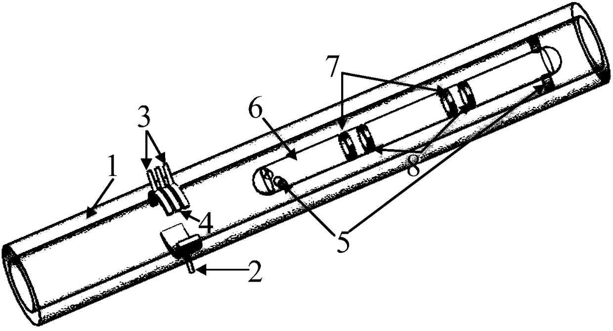
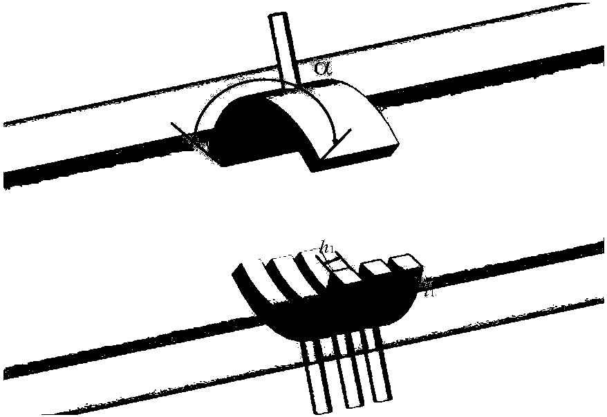
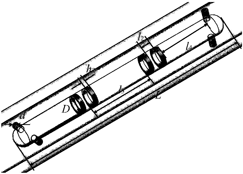

Image

  • Oil-well low-liquid-producing high-water-containing oil-water-two-phase-flow flow measuring method
  • Oil-well low-liquid-producing high-water-containing oil-water-two-phase-flow flow measuring method
  • Oil-well low-liquid-producing high-water-containing oil-water-two-phase-flow flow measuring method

Examples


Embodiment Construction

[0027] The invention proposes a method for measuring the flow rate of oil-water two-phase flow with low fluid production and high water content in oil wells. In terms of total flow measurement, an insertion-type conductance-related flowmeter is installed in the collecting channel of the collecting-type instrument, which has a significant role in flow pattern regulation and can ensure that the annular flow space between the insert body and the inner wall of the collecting channel has a stable internal flow rate. Based on the flow structure, it is beneficial to obtain the correlation between the upstream and downstream measurement electrode signals of the plug-in conductivity sensor with high reliability and repeatability. Experiments show that at low flow rates, the relative flow rate of the plug-in conductance-related flowmeter only has a good linear relationship with the total flow rate of the oil-water two-phase flow, and has nothing to do with the water cut. In terms of wat...


PUM


Abstract

The invention relates to an oil-well low-liquid-producing high-water-containing oil-water-two-phase-flow flow measuring method. Two sets of sensors located in the same sensor pipeline are adopted to be combined for measuring, one set of sensors is an upstream-downstream electric conduction sensor array, and the other set of sensors is arc-shaped opposite-wall-type electric conduction sensors. Themethod comprises the following measuring steps that through the upstream-downstream electric conduction sensor array, upstream-downstream fluid fluctuating signals are obtained, the oil-water-two-phase-flow relevant flowing speed Ucc is calculated through a relevant algorithm, and the mixed flowing speed Um is obtained accordingly; through the arc-shaped opposite-wall-type electric conduction sensors, the normalized electric conduction rate Ge* is obtained, and the water holding ratio Yw and the oil holding ratio Yo are obtained through calculation accordingly; and the phase distribution coefficient C0 and bubble diameter index N in an oil water-two-phase-flow drifting model are determined, physical correlation between the mixed flowing speed Um and the oil phase appearance flowing speed Uso as well as the oil holding ratio Yo and the oil phase appearance flowing speed Uso is achieved, and measuring of the oil phase appearance flowing speed Uso is achieved; and the water phase appearance flowing speed is obtained.

Description

technical field [0001] The invention relates to the technical field of production profile logging of oil-water two-phase flow with low fluid production and high water cut in oil wells during the high water cut period of low permeability reservoirs. Background technique [0002] Oil-water two-phase flow commonly exists in the production process of oil wells in the petroleum industry. The main task of oil well dynamic monitoring technology is to correctly evaluate the production characteristics of oil wells and accurately measure the layered phase separation flow of oil and gas reservoirs, so as to provide scientific basis for the adjustment of oilfield development plans. However, as my country's continental low-yield and low-permeability old oilfields enter the stage of high water-cut production, there is a serious slippage effect between the oil and water phases (relative movement between phases), and the local flow velocity and local concentration of the dispersed phase are ...

Claims


Application Information

Patent Timeline
IPC IPC(8): E21B47/00E21B49/08
CPCE21B47/00E21B49/087
Inventor 金宁德何元生翟路生任英玉
Owner TIANJIN UNIV
Learn More