A kind of biomass processing device and its system
A biomass treatment and biomass technology, applied in the direction of biofuel, waste fuel, fuel, etc., can solve the problems of physical and chemical properties restricting the development of biomass molding industry, short life of molding vulnerable parts, high temperature and pressure, etc., to achieve Low loss, strong water resistance, and reduced storage costs
- Summary
- Abstract
- Description
- Claims
- Application Information
AI Technical Summary
Problems solved by technology
Method used
Image
Examples
Embodiment 1
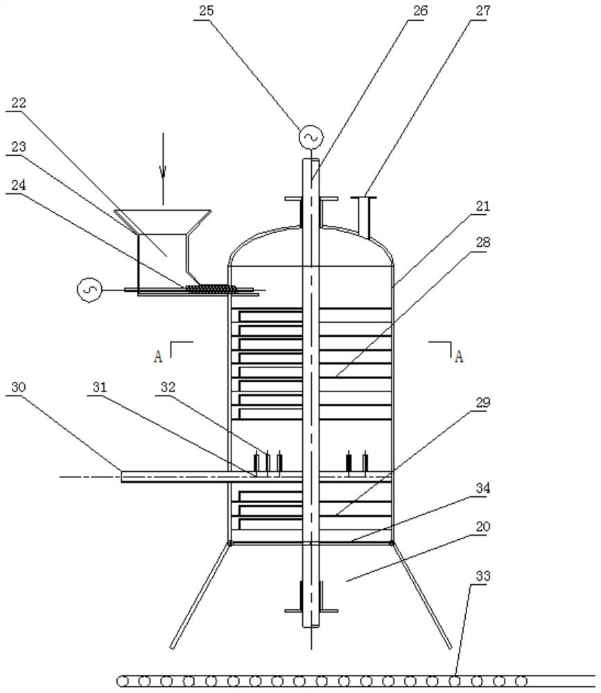
[0041] use as figure 2Processing device shown. The biomass treatment device includes a cylinder body. Biomass enters the interior of the cylinder body from a material inlet on the upper part of the cylinder body. A spring-loaded material plate is arranged at the material inlet to facilitate the opening and closing of the material inlet. The heating medium inlet is set on the cylinder wall, especially keeping a certain distance from the material inlet. The heating medium inlet can be selected to extend into the pipeline in the cylinder. There are nozzles evenly distributed on the pipeline, and the heating medium is introduced into the cylinder through the nozzles. The nozzles can be Distributed along the pipeline, it is also possible to set the spout towards the direction of the material inlet. The cylinder above the heating medium inlet is a heating chamber. After the material enters the cylinder, it falls on the rotating mechanism. The rotating mechanism is driven to rotate...
Embodiment 2
[0044] use as Figure 5 Processing device shown. The biomass treatment device includes a cylinder body. Biomass enters the interior of the cylinder body from a material inlet on the upper part of the cylinder body. A spring-loaded material plate is arranged at the material inlet to facilitate the opening and closing of the material inlet. The heating medium inlet is set on the cylinder wall, especially keeping a certain distance from the material inlet. The heating medium inlet can be selected to extend into the pipeline in the cylinder. There are nozzles evenly distributed on the pipeline, and the heating medium is introduced into the cylinder through the nozzles. The nozzles can be Distributed along the pipeline, it is also possible to set the spout towards the direction of the material inlet. The cylinder above the heating medium inlet is a heating chamber. After the material enters the cylinder, it falls on the rotating mechanism. The rotating mechanism is driven to rotat...
Embodiment 3
[0047] The biomass treatment device includes a cylinder body. Biomass enters the interior of the cylinder body from a material inlet on the upper part of the cylinder body. A spring-loaded material plate is arranged at the material inlet to facilitate the opening and closing of the material inlet. The heating medium inlet is set on the cylinder wall, especially keeping a certain distance from the material inlet. The heating medium inlet can be selected to extend into the pipeline in the cylinder. There are nozzles evenly distributed on the pipeline, and the heating medium is introduced into the cylinder through the nozzles. The nozzles can be Distributed along the pipeline, it is also possible to set the spout towards the direction of the material inlet. spring separator as Figure 7 shown. The cylinder above the heating medium inlet is a heating chamber. After the material enters the cylinder, it falls on the rotating mechanism. The rotating mechanism is driven to rotate by ...
PUM
 Abstract
Description
Claims
Application Information
 - R&D
- Intellectual Property
- Life Sciences
- Materials
- Tech Scout
- Unparalleled Data Quality
- Higher Quality Content
- 60% Fewer Hallucinations
Browse by: Latest US Patents, China's latest patents, Technical Efficacy Thesaurus, Application Domain, Technology Topic, Popular Technical Reports.
© 2025 PatSnap. All rights reserved.Legal|Privacy policy|Modern Slavery Act Transparency Statement|Sitemap|About US| Contact US: help@patsnap.com


